The most obvious application for a Raspberry Pi is re-creating the sliding red lights found on “KITT” from Knight Rider or the Cylons in Battestar Galactica. This can all be done with pure electronics but that doesn’t involve any programming and therefore isn’t as cool.
So here is a brief description of my “running lights” project. It may be overkill to throw an entire computer at such a task but it served a number of purposes :
- good introduction to Python GPIO programming
- good introduction to Raspberry Pi GPIO interfacing
- good practice at soldering, wiring, testing and constructing an electronic circuit
It isn’t my intention to show you how to create the circuit board but hopefully there is enough information on this page to help you get started.
Raspberry Pi Parts
- Raspberry Pi
- Debian image on SD card
- RPi.GPIO library installed
Components
- 10 5mm Red LEDs (£1.50)
- 10 560ohm resistors (£0.10)
- 10 27Kohm resistors (£0.10)
- 10 BC548 NPN transistors (£1.00)
- 1 Stripboard (£3.50)
- 12 lengths of wire
- 1 0.1″ Crimp connector housing 1×3 pin (£0.05)
- 2 0.1″ Crimp connector housing 1×10 pin (£0.40)
- 12+ Female crimp pins for 0.1″ housings (£0.60)
Tools
- Wirecutters/stripers
- Soldering iron + solder
- 1 Stripboard cutter Tool (Spot Face Cutter)
In total the board cost me approximately £10 in bits but it really depends on what components and tools you already have. I didn’t need to buy solder or a stripboard cutter but I did spend £12 on a new wire stripper. If you plan on doing any work with stripboard a “stripboard cutter” or “spot cutter” is well worth a few pounds/dollars.
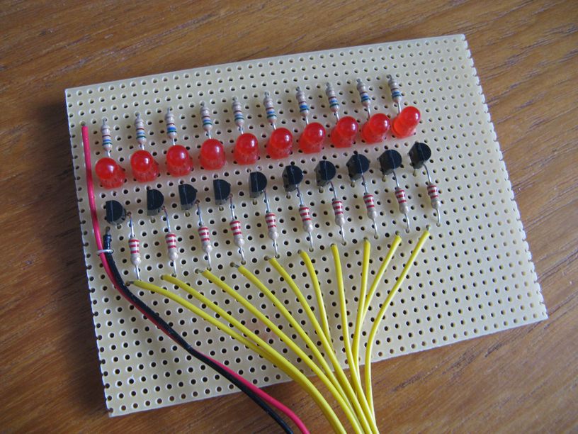
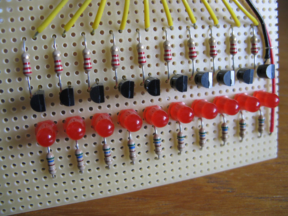
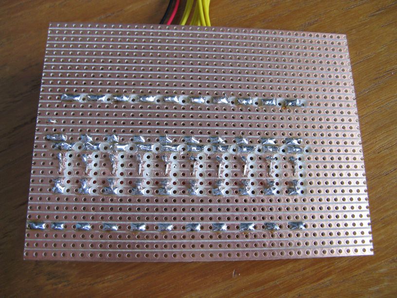
The photos below show my scripboard with the 10 LEDs, resistors and transistors soldered in place. Each LED requires 1 560ohm resistor, 1 27Kohm resistor and 1 BC548 transistor.


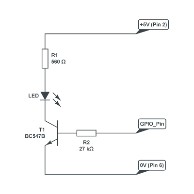
Each LED is wired as shown in the following diagram :
Given the low current required the transistor can replaced with any device that can supply the LED with 5mA. So BC547 or BC548 devices are perfect.
I didn’t worry which LED I connected to which GPIO pin. Once the circuit was working I corrected the light sequence in the Python code to put them in the correct order.
Python Program
This is the Python program I used to sequentially turn the LEDs on an off. It uses the RPi.GPIO library so that must installed already.
#------------------------------------------------
# Name: Running Lights
# Author    : matt.hawkins
# Created   : 21/06/2012
# Python    : 2 or 3
# Copyright : (c) matt.hawkins 2012
#------------------------------------------------
#!/usr/bin/env python

# Import required libraries
import time
import RPi.GPIO as GPIO

# Use BCM GPIO references
# instead of physical pin numbers
GPIO.setmode(GPIO.BCM)

# Define GPIO signals to use
# that are connected to 10 LEDs
# Pins 7,11,15,21,23,16,18,22,24,26
# GPIO4,GPIO17,GPIO22,GPIO9,GPIO11
# GPIO23,GPIO24,GPIO25,GPIO8,GPIO7
RpiGPIO = [4,17,22,9,11,23,24,25,8,7]

# Set all pins as output
for pinref in RpiGPIO:
  print("Setup pins")
  GPIO.setup(pinref,GPIO.OUT)

# Define some settings
StepCounter = 0
StepDir = 1
WaitTime = 0.2

# Define some sequences

# One LED
StepCount1 = 10
Seq1 = []
Seq1 = list(range(0,StepCount1))
Seq1[0] =[1,0,0,0,0,0,0,0,0,0]
Seq1[1] =[0,1,0,0,0,0,0,0,0,0]
Seq1[2] =[0,0,1,0,0,0,0,0,0,0]
Seq1[3] =[0,0,0,1,0,0,0,0,0,0]
Seq1[4] =[0,0,0,0,1,0,0,0,0,0]
Seq1[5] =[0,0,0,0,0,1,0,0,0,0]
Seq1[6] =[0,0,0,0,0,0,1,0,0,0]
Seq1[7] =[0,0,0,0,0,0,0,1,0,0]
Seq1[8] =[0,0,0,0,0,0,0,0,1,0]
Seq1[9] =[0,0,0,0,0,0,0,0,0,1]

# Double LEDs
StepCount2 = 11
Seq2 = []
Seq2 = list(range(0,StepCount2))
Seq2[0] =[1,0,0,0,0,0,0,0,0,0]
Seq2[1] =[1,1,0,0,0,0,0,0,0,0]
Seq2[2] =[0,1,1,0,0,0,0,0,0,0]
Seq2[3] =[0,0,1,1,0,0,0,0,0,0]
Seq2[4] =[0,0,0,1,1,0,0,0,0,0]
Seq2[5] =[0,0,0,0,1,1,0,0,0,0]
Seq2[6] =[0,0,0,0,0,1,1,0,0,0]
Seq2[7] =[0,0,0,0,0,0,1,1,0,0]
Seq2[8] =[0,0,0,0,0,0,0,1,1,0]
Seq2[9] =[0,0,0,0,0,0,0,0,1,1]
Seq2[10]=[0,0,0,0,0,0,0,0,0,1]

# Two LEDs from opposite ends
StepCount3 = 9
Seq3 = []
Seq3 = list(range(0,StepCount3))
Seq3[0] =[1,0,0,0,0,0,0,0,0,1]
Seq3[1] =[0,1,0,0,0,0,0,0,1,0]
Seq3[2] =[0,0,1,0,0,0,0,1,0,0]
Seq3[3] =[0,0,0,1,0,0,1,0,0,0]
Seq3[4] =[0,0,0,0,1,1,0,0,0,0]
Seq3[5] =[0,0,0,1,0,0,1,0,0,0]
Seq3[6] =[0,0,1,0,0,0,0,1,0,0]
Seq3[7] =[0,1,0,0,0,0,0,0,1,0]
Seq3[8] =[1,0,0,0,0,0,0,0,0,1]

# Choose a sequence to use
Seq = Seq3
StepCount = StepCount3

# Start main loop
while True:
  print("-- Step : "+ str(StepCounter) +" --")
  for pinref in range(0, 10):
    xpin=RpiGPIO[pinref]#
    # Check if LED should be on or off
    if Seq[StepCounter][pinref]!=0:
      print(" Enable " + str(xpin))
      GPIO.output(xpin, True)
    else:
      print(" Disable " + str(xpin))
      GPIO.output(xpin, False)

  StepCounter += StepDir

  # If we reach the end of the sequence reverse
  # the direction and step the other way
  if (StepCounter==StepCount) or (StepCounter<0):
    StepDir = StepDir * -1
    StepCounter = StepCounter + StepDir + StepDir

  # Wait before moving on
  time.sleep(WaitTime)
This script can be downloaded from my BitBucket repository using this link or directly to your Pi using :
wget https://bitbucket.org/MattHawkinsUK/rpispy-misc/raw/master/python/10_led_running_lights_1.py
The script can be run using :
python 10_led_running_lights_1.py
Here is a video showing Sequence 3 running :
Updated Script
Since this particle was written I’ve created a modified version of this script which accepts command line parameters to set the sequence and delay between LED switching.
This script can be downloaded from my BitBucket repository using this link or directly to your Pi using :
wget https://bitbucket.org/MattHawkinsUK/rpispy-misc/raw/master/python/10_led_running_lights_2.py
The script can be run using :
python 10_led_running_lights_2.py
or :
python 10_led_running_lights_2.py 2 0.3
where “2” is the sequence and “0.3” is the delay in seconds between the LEDs.
I put other Raspberry Pi related videos on my YouTube channel Raspberry Pi playlist.
31 Comments
The prices in brackets are the total cost for that number of items. To keep the price down you may have to order more than the required number. For example I ordered resistors in packs of 100 for 99p on ebay. In general ordering the components online was much cheaper than going to a shop. I bought the stripboard from Maplin but I’m sure it would be cheaper online.
Having just tried the code you pasted above, python had a go about the use of the singe = in the condition of the “while StepCounter=0:” part of the algorithm.
I’ve also found that using “while StepCounter==0:” only executes the first run, but changing it to “while 1:” will make it continuously loop.
Thanks for posting the article, just thought I’d make it aware that there are problems with the code that was pasted above.
Somehow I managed to paste the wrong script into the article. I’ve updated it now.
I see from your code that you use pins 11 through to 20. I have downloaded a spreadsheet listing all the GPIO pins and it says do not connect to pins 4, 6, 14, 17, 20 and 26. I have no idea why it says not to use them – and I haven’t in my projects – but they seem to work for you.
Do you have any idea why there are warnings not to use the pins?
I do not use Pin 4. The numbers 4,17,21,22,10,8,11,23,24,25 are GPIO references not Pin nu4mbers. “4” is GPIO4 which is Pin 7 for example.
Nice example!
Hi.
It seems that the python source code listing is truncated in the middle of a statement.
Thanks for pointing it out. WordPress has a problem with “less than” signs. Should be fixed now.
Can’t get it to work. Syntax error in line 80 which reads:- while 1==1. This line was the subject of an earlier post and you changed it. Is there something missing? The picture is not terribly clear so do I need to connect live to pin 1 and ground to pin 6. I’m using a breadboard. It’s my first project with multiple LEDs and my first bash at electronics (the subject was not taught in school when I left in 1959), also first attempt at Python.
Just noticed that line 80 changed in above to while True:. It still does not work!
What is the full syntax error? Make sure the indentation is correct as this is vital in Python. I’ve updated the diagram as the “power source” symbol was confusing. Pin 2 and Pin 6 on the Pi provide +5V and 0V to the circuit.
This program is getting on my nerves. It seems to be so full of sytax errors that, as a newbie, I am concerned that it has not been tried and tested thoroughly on a RaspberryPi. If this is the case then, Matt, you should be ashamed of youself. I have now found and installed the module by using python3, but I now get an error on line 20. Sort it out, please. I am not going to apologise for my tone – I have been a professional all my life and have never published work that is unchecked and does not conform to high standards of working practices. If this gets modded out then be sure I have a copy to post eleswhere. Do the job properly or don’t do it at all.
Works fine for me. Must be your dodgy soldering. I have never used Python 3 but feel free to write your own programme and publish that.
David, you need to calm down and get a grip
1) Most of your issues so far have been caused by syntax errors due to your careless typing.
2) You are trying to use Python 3.
3) You are trying to use WiringPi when I clearly state you need to use RPi.GPIO.
4) My Youtube video shows my script working.
5) It’s not my fault if you can’t tell the difference between curved and square brackets.
I am happy to correct any errors in my articles as they are reported. This is a hobby and the information is provided “as is”. If you don’t like my posts then you are welcome to go some place else. Please don’t threaten me over something so trivial as a bit of Python code. It is embarrassing. For you.
Would love to see your published work given you are clearly an expert in some other field. I hope it isn’t medicine or aircraft engineering.
In your code:
RpiGPIO = [4,17,21,22,10,8,11,23,24,25]
# Set all pins as output
for pin in RpiPins:
print “Setup pins”
GPIO.setup(pin,GPIO.OUT)
Shouldn’t RpiGPIO be RpiPins? Otherwise RpiPins is undefined at the time of the for.
Thanks I’ve updated it now. I changed the script to use BCM GPIO numbers and the array got renamed.
Just for clarity. No typing errors apart from that uppercase W. I used copy and paste into leafpad. No soldering; using breadboard. After you first published this you had to alter it. Even after my ‘rant’ you had to alter it again introducing GPIO BCM. Hence, I am justified in my comments. I did use RPi.GPIO which I downloaded and installed per your instructions. I also downloaded WiringPi from this site thinking it must be useful for something because it was here. If I am wrong then I am wrong andf old enough to admit it. Can you say the same?
Not all updates to my site are the result of your comments. This isn’t the 1960s. Web pages are not slabs of stone. They get updated whenever the author feels like it. I switched to using BCM references because it is a better way to do things. You did not download WiringPi from my site. I’ve never used WiringPi, don’t provide downloads of it and don’t use it in any of my scripts. I think you are confused. Again.
Nice little demo, but why the transistors?
I appreciate you might want to do it for demo purposes, (to demonstrate driving higher loads), but the Pi is more than capable of driving small LEDs directly to do this sort of thing – especially the 5mA load you’re presenting it with here…
e.g. while I’d not recomend running this for very long (it does exceede some specs. notably the 3.3v regulator!) http://unicorn.drogon.net/pi17leds.jpg works just fine. Each LED here is pulling 10mA, so 170mA in total – the worst that would happen here is that the 3.3v reg. would shut down and the Pi reboot.
-Gordon
I didn’t want to encourage people to draw current directly from the GPIO pins because when they moved onto other devices (buzzers etc) they may damage their Pi. Some users may not appreciate the limits so I decided to play it safe from the start. This way they can use whatever size LEDs they like without drawing too much current. Also it means you can have a standard setup and swap between LEDs, buzzers and small motors.
Hi,
How can i generate random led flasher with raspberry.
for example i have 5 led and 1 button.
So if i press the button, random led will flash on.
You could use one of my BerryClip example scripts as a starting point for this script : https://bitbucket.org/MattHawkinsUK/rpispy-berryclip/raw/master/berryclip_09.py
You would need to change the “LedSeq” array of GPIO references to match your LED wiring. The script starts lighting the LEDs straight away so you would need to add something at the beginning to wait for a switch press.
Ok, I’ll try it first.
Thank you so much. 🙂
Oya, is it random in python is real random?
I mean there is no pattern in random.
It’s as random as you can get on a computer. For the purposes of LED flashing it will look random with no pattern.
xpin = RpiGPIO[pin]if Seq[StepCounter][pin]!=0:
should be
xpin = RpiGPIO[pin]
if Seq[StepCounter][pin]!=0:
Hi Paul, you are right. For some reason WordPress losing the line break.Nothing I do will correct it. There is a line break there but it is getting lost when the page renders. I’ve added a # to separate the lines. This should get ignored by Python.
It would be cool if the python asked which led sequence to run. I.e. 1, 2 or 3
Hi MATT,
I know your great script has been around awhile, but I really like it. Built it using a RPi few years ago. Now I’m fighting a problem of trying to run each Seq one after another. Would like spend 20 seconds on each. The Seq and StepCount are in setup. If I try to set up time.time() in the main loop, I get crashes and other no good results. Or one Seq doesn’t see the timeout and the next Seq doesn’t start. Maybe I could try the Whiptail menu system that is used in the Pi? Just need push in the right direction. It sure could be a good demo switching from one Seq to another. Thanks
I’ve just updated this script (after 5 years!) to work with Python 3. I’ve also added a new script which takes command line parameters. As you mention Whiptail I guess you are mixing with some other scripting language? If I was going to modify this script to loop through sequences I would probably combine all the sequences into 1 array and then just loop through chunks of that array as required. I may give it a go now I’ve dug out my original LED board and a Model B.
Matt
Sure glad you updated the old script with the 2 neat command line options. I’m definitely going to try it.
FYI: I’m able to run the LEDs just fine with only 330 ohm 1/6 watt resistors. I use 3.3 volts from the Pi Zero to all the LEDs anodes tied together. Each cathode has the resistor. Other side goes to proper pin of the Pi. I then reverse the True and False of main loop code. Nothing feels hot at all. I do realize you wanted to show the safer way of wiring the hardware. Thanks so much for staying with the project. I think Knight-Rider coding will be around forever!
The transistors are a bit over the top but as this was one of my first projects I was being super careful. These days if need a few LEDs I use the technique you describe and just wire up directly to the GPIO pins with a 330ohm resistor.