
Once you’ve played with LEDs, switches and stepper motors the next natural step is 16×2 alphanumeric LCD modules. These modules are cheap (less than $10) and easy to interface to the Raspberry Pi. They have 16 connections but you only need to use 6 GPIO pins on your Pi.
Most of the 16×2 modules available are compatible with the Hitachi HD44780 LCD controller. This allows you to buy almost any device and be sure it is going to work in much the same way as any other. There are loads to choose from on eBay with different coloured backlights. The one I purchased had a blue backlight.
LCD Module Hardware
 The pinout of the module is :
- Ground
- VCC (Usually +5V)
- Contrast adjustment (VO)
- Register Select (RS).
RS=0: Command, RS=1: Data - Read/Write (R/W).
R/W=0: Write, R/W=1: Read - Enable
- Bit 0 (Not required in 4-bit operation)
- Bit 1 (Not required in 4-bit operation)
- Bit 2 (Not required in 4-bit operation)
- Bit 3 (Not required in 4-bit operation)
- Bit 4
- Bit 5
- Bit 6
- Bit 7
- LED Backlight Anode (+)
- LED Backlight Cathode (-)
Usually the device requires 8 data lines to provide data to Bits 0-7. However the device can be set to a “4 bit” mode which allows you to send data in two chunks (or nibbles) of 4 bits. This is great as it reduces the number of GPIO connections you require when interfacing with your Pi.
Here is how I wired up my LCD :
| LCD Pin | Function | Pi Function | Pi Pin |
| 01 | GND | GND | P1-06 |
| 02 | +5V | +5V | P1-02 |
| 03 | Contrast | GND | P1-06 |
| 04 | RS | GPIO7 | P1-26 |
| 05 | RW | GND | P1-06 |
| 06 | E | GPIO8 | P1-24 |
| 07 | Data 0 | ||
| 08 | Data 1 | ||
| 09 | Data 2 | ||
| 10 | Data 3 | ||
| 11 | Data 4 | GPIO25 | P1-22 |
| 12 | Data 5 | GPIO24 | P1-18 |
| 13 | Data 6 | GPIO23 | P1-16 |
| 14 | Data 7 | GPIO18 | P1-12 |
| 15 | +5V via 560ohm | ||
| 16 | GND | P1-06 |
NOTE : The RW pin allows the device to be be put into read or write mode. I wanted to send data to the device but did not want it to send data to the Pi so I tied this pin to ground. The Pi can not tolerate 5V inputs on its GPIO header. Tying RW to ground makes sure the device does not attempt to pull the data lines to 5V which would damage the Pi.
In order to control the contrast you can adjust the voltage presented to Pin 3. This must be between 0 and 5V. I tied this pin to ground.
Pin 15 provides 5V to the backlight LED. It wasn’t clear on my device if this could be connected direct to 5V so I played safe and placed a 560ohm resistor in line with this pin.

Wiring Checks
Here are some sanity checks before you power up your circuit for the first time :
- Pin 1 (GND), 3 (Contrast), 5 (RW) and 16 (LED -) ( should be tied to ground.
- Pin 2 should be tied to 5V. Pin 15 should have a resistor inline to 5V to protect the backlight.
- Pin 7-10 are unconnected
- Pin 11-14 are connected to GPIO pins on the Pi
Python
You can control a HD44780 style display using any programming environment you like but my weapon of choice is Python. I use the RPi.GPIO library to provide access to the GPIO.
Here is my code :
#!/usr/bin/python
#--------------------------------------
# ___ ___ _ ____
# / _ \/ _ \(_) __/__ __ __
# / , _/ ___/ /\ \/ _ \/ // /
# /_/|_/_/ /_/___/ .__/\_, /
# /_/ /___/
#
# lcd_16x2.py
# 16x2 LCD Test Script
#
# Author : Matt Hawkins
# Date : 06/04/2015
#
# https://www.raspberrypi-spy.co.uk/
#
#--------------------------------------
# The wiring for the LCD is as follows:
# 1 : GND
# 2 : 5V
# 3 : Contrast (0-5V)*
# 4 : RS (Register Select)
# 5 : R/W (Read Write) - GROUND THIS PIN
# 6 : Enable or Strobe
# 7 : Data Bit 0 - NOT USED
# 8 : Data Bit 1 - NOT USED
# 9 : Data Bit 2 - NOT USED
# 10: Data Bit 3 - NOT USED
# 11: Data Bit 4
# 12: Data Bit 5
# 13: Data Bit 6
# 14: Data Bit 7
# 15: LCD Backlight +5V**
# 16: LCD Backlight GND
#import
import RPi.GPIO as GPIO
import time
# Define GPIO to LCD mapping
LCD_RS = 7
LCD_E = 8
LCD_D4 = 25
LCD_D5 = 24
LCD_D6 = 23
LCD_D7 = 18
# Define some device constants
LCD_WIDTH = 16 # Maximum characters per line
LCD_CHR = True
LCD_CMD = False
LCD_LINE_1 = 0x80 # LCD RAM address for the 1st line
LCD_LINE_2 = 0xC0 # LCD RAM address for the 2nd line
# Timing constants
E_PULSE = 0.0005
E_DELAY = 0.0005
def main():
# Main program block
GPIO.setwarnings(False)
GPIO.setmode(GPIO.BCM) # Use BCM GPIO numbers
GPIO.setup(LCD_E, GPIO.OUT) # E
GPIO.setup(LCD_RS, GPIO.OUT) # RS
GPIO.setup(LCD_D4, GPIO.OUT) # DB4
GPIO.setup(LCD_D5, GPIO.OUT) # DB5
GPIO.setup(LCD_D6, GPIO.OUT) # DB6
GPIO.setup(LCD_D7, GPIO.OUT) # DB7
# Initialise display
lcd_init()
while True:
# Send some test
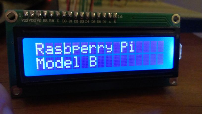
lcd_string("Rasbperry Pi",LCD_LINE_1)
lcd_string("16x2 LCD Test",LCD_LINE_2)
time.sleep(3) # 3 second delay
# Send some text
lcd_string("1234567890123456",LCD_LINE_1)
lcd_string("abcdefghijklmnop",LCD_LINE_2)
time.sleep(3) # 3 second delay
# Send some text
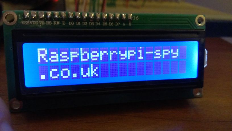
lcd_string("RaspberryPi-spy",LCD_LINE_1)
lcd_string(".co.uk",LCD_LINE_2)
time.sleep(3)
# Send some text
lcd_string("Follow me on",LCD_LINE_1)
lcd_string("Twitter @RPiSpy",LCD_LINE_2)
time.sleep(3)
def lcd_init():
# Initialise display
lcd_byte(0x33,LCD_CMD) # 110011 Initialise
lcd_byte(0x32,LCD_CMD) # 110010 Initialise
lcd_byte(0x06,LCD_CMD) # 000110 Cursor move direction
lcd_byte(0x0C,LCD_CMD) # 001100 Display On,Cursor Off, Blink Off
lcd_byte(0x28,LCD_CMD) # 101000 Data length, number of lines, font size
lcd_byte(0x01,LCD_CMD) # 000001 Clear display
time.sleep(E_DELAY)
def lcd_byte(bits, mode):
# Send byte to data pins
# bits = data
# mode = True for character
# False for command
GPIO.output(LCD_RS, mode) # RS
# High bits
GPIO.output(LCD_D4, False)
GPIO.output(LCD_D5, False)
GPIO.output(LCD_D6, False)
GPIO.output(LCD_D7, False)
if bits&0x10==0x10:
GPIO.output(LCD_D4, True)
if bits&0x20==0x20:
GPIO.output(LCD_D5, True)
if bits&0x40==0x40:
GPIO.output(LCD_D6, True)
if bits&0x80==0x80:
GPIO.output(LCD_D7, True)
# Toggle 'Enable' pin
lcd_toggle_enable()
# Low bits
GPIO.output(LCD_D4, False)
GPIO.output(LCD_D5, False)
GPIO.output(LCD_D6, False)
GPIO.output(LCD_D7, False)
if bits&0x01==0x01:
GPIO.output(LCD_D4, True)
if bits&0x02==0x02:
GPIO.output(LCD_D5, True)
if bits&0x04==0x04:
GPIO.output(LCD_D6, True)
if bits&0x08==0x08:
GPIO.output(LCD_D7, True)
# Toggle 'Enable' pin
lcd_toggle_enable()
def lcd_toggle_enable():
# Toggle enable
time.sleep(E_DELAY)
GPIO.output(LCD_E, True)
time.sleep(E_PULSE)
GPIO.output(LCD_E, False)
time.sleep(E_DELAY)
def lcd_string(message,line):
# Send string to display
message = message.ljust(LCD_WIDTH," ")
lcd_byte(line, LCD_CMD)
for i in range(LCD_WIDTH):
lcd_byte(ord(message[i]),LCD_CHR)
if __name__ == '__main__':
try:
main()
except KeyboardInterrupt:
pass
finally:
lcd_byte(0x01, LCD_CMD)
lcd_string("Goodbye!",LCD_LINE_1)
GPIO.cleanup()This script can be downloaded using this link or directly to your Pi using the following command :
wget https://bitbucket.org/MattHawkinsUK/rpispy-misc/raw/master/python/lcd_16x2.py
It can then be run using :
sudo lcd_16x2.py
If you use this code the only thing you will need to change is the GPIO pin mapping depending on what pins you use on your Pi GPIO header. Here are some photos :
Additional Notes : RS is low when sending a command to the LCD and high when sending a character. RW is always low to ensure we only ever input data into the module. 8 bit bytes are sent 4 bits at a time. Top 4 bits first and the last 4 bits second. Delays are added between certain steps to ensure the module can react to the signal before it changes.
The code above was inspired by code submitted by ‘texy’ on the RaspberryPi.org forum. I changed the way the bytes are broken down to bits as this significantly increased the response time of the display.
Troubleshooting
If you are having issues then try :
- Double check the wiring.
- Try adjusting the voltage on the contrast pin between 0V and 3.3V.
- Change the E_PULSE and E_DELAY parameters from 0.0005 to 0.001. Some screens are sensitive to these times and won’t initialise if they are too small.
- Use Python 2. I haven’t tested with Python 3 yet.
Take a look at my other LCD Screen related posts which include details of the 20×4 version of the screen used in this post.
102 Comments
Hi,
your example works fine but i’m hving problems using 20×4 LCD – what do I need to change in the script to show all 4 lines?
thanks, dex
I haven’t got a 20×4 LCD so I can’t check this but try …
Change LCD_WIDTH = 16 to LCD_WIDTH = 20
Update the line addresses to :
LCD_LINE_1 = 0x80 # LCD RAM address for the 1st line
LCD_LINE_2 = 0xC0 # LCD RAM address for the 2nd line
LCD_LINE_3 = 0x94 # LCD RAM address for the 3rd line
LCD_LINE_4 = 0xD4 # LCD RAM address for the 4th line
This french site uses this python code but for a 4×20 display
Indeed the lines addresses are:
LCD_LINE = [ 0x80 , 0xC0 , 0x94 , 0xD4 ] # LCD RAM address for 4 lines
I cover 20×4 screens in this tutorial : 20×4 LCD Module Control Using Python
Sorry Mr, i want to ask.
I use raspberry pi 2 type b. pin 19 until 24 already for a RFID.
how to changed pin?
You can use different GPIO pins but you must update the LCD_D4,LCD_D5,LCD_D6 and LCD_D7 variables in the script.
Hmm, am I misreading something or is there some confusion under
“Here is how I wired up my LCD”
you say you wire LCD pin 1 to +5V p1_02 – but the LCD pin 01 is GND right?
So under “Here is how I wired up my LCD” the LCD pin 01 should actually be to GND (p1_06) and LCD pin 02 to +5V (p1_02)?
And in the schematics and “Wiring Checks” you say connect pin 1 to GND.
Am I just tired and misreading?
Thanks for the tutorial, making my way through it now! Just wanted to ask you that 🙂
You are correct. Thanks for spotting it. I’ve updated the table . LCD Pin 1 is Ground and Pin 2 is +5V.
Very nice tutorial, but there is another slight mistake. Under “Here is how I wired up my LCD” you used GPIO 7 and 8 for RS and E, but in your python code you set RS to 26 and E to 24. I had to change these lines to get my LCD working.
Thanks Markus. I’ve corrected it now. The example uses GPIO pins that make the breadboard diagram easier but this is different to my real test circuit. I got confused between the two!
hi I’m getting stuck with this, i cant get any output from the screen. It’s lit but nothing when I run the code.
1. I’m running 2.7 python
2. I’m running Raspbian
3. I’m running the RPi.GPIO-0.3.1a
4. I’m running python-rpi.gpio_0.3.1a-1_armhf.deb
5. And i’m pretty sure my wireing is correct.
Was a problem with my contrast pin (3) fixed now 🙂
Hi Matt.
Thank you for this tutorial.
I had a problem.
When the python’s script has finished, display fills by 32 characters of “inverted P”.
Here is video:
http://youtu.be/mrIJaIcRGkE
It caused probably by electomagnetic noise (long wires between Raspberry and display).
http://www.astromik.org/raspi/dis-wired.jpg
I solved this problem attaching resistor 150k between pins 2 and 6 on the display port.
Here is a picture:
http://www.astromik.org/raspi/dis-resistor.jpg
Now is all OK.
—
… excuse my english 🙂
I think this is because when the script finishes the RPi.GPIO library configures all the pins as inputs. This leaves the Enable pin floating. Adding a resistor pulls it high so the screen doesn’t reset. I might give this a try on my circuit.
i wired my screen up the same as yours but its VERY dark.
theres no colour to the screen (i.e blue) and the character blocks are barely visible.
using a 3.3k resistor as i couldnt find a 5600ohm. only other ones i have are 10k, 430, 330 resistors
The LED backlight resistor is 560 ohm not 5600 ohm. If you are using 3.3K then the LED isn’t getting enough current. Use a 430 instead and that should light up the screen a bit better.
I have gotten everything wired up and double checked everything, though I only get squares all the way across the LCD screen. I re wired everything just to make sure it was done correctly, still the same issue.
Any ideas?
Side note: I am also a bit unsure on the need for the resistor, the LCD can operate between 2.7 to 5.5V. Is the resistors purpose to stop the LCD from pulling more than 5v?
All fixed, was connectivity issues with the squares showing up. Once I had fixed that problem I then started getting weird characters showing up. That was also fixed by setting up my locale settings OR by ignoring what the SSH client sent as a locale. Everything is working good now, nice tutorial! Bit confusing in parts though.
how did you fixed the squares issues? I have the same problem and I can´t find any help.
Double check the contrast pin. Try varying the voltage between 0V and 3.3V.
The resistor is for the LED backlight not the LCD itself. It usually isn’t clear but some LCD modules do not include a resistor to limit the current drawn by the LED backlight. So I always put one in to be sure.
Thanks for the great tutorial.
I’ve tried this and have a worrying problem. I don’t see any text, just black squares accross the lower line of the display. What concerns me is that the data lines each read 5v when I run the Python script.
Pin 5 is *definitely* grounded, and since the Pi should only ouput 3.3v on these pins I’m guessing this must mean a fault in the LCD?
Any suggestions would be greatly appreciated.
Many thanks,
Matt
Unhelpfully I’ve signed the above comment “Matt”. Apologies!
I wired up exactly as seen in the diagram and ran the script. BUT lcd shows nothing. I checked my wiring and even program 2-3 times bit nothing helped.
What do you think, what’s the problem??
(This is my first gpio program.)
Nice tutorial. In case someone’s looking for a full library for the HD44780 on the Raspberry Pi, here’s my attempt at doing so: https://github.com/dbrgn/RPLCD It’s tested both on 20×4 and 16×2 LCDs and provides test scripts to verify your wiring.
Pingback: Afficheur LCD sur Raspberry Pi | Anderson69s
Pingback: 16×2 LCD Modülünü Bağladık! - Raspberry Pi Türkiye Topluluğu
Hello,
I have just started with python and have a problem with the code.
I am getting a invalid syntax error on a simple instruction.-
lcd_string(“Raspberry Pi”) in the 16×2 LCD Module Control
Where have I went wrong. thank you..
Hey, i was wandering: can i use a 330R resistor instead of the 630ohm?? If not can i use any of the following: 10k 1k0? Please reply ASAP! Thanks in advance and AMAZING tutorial!! (i had trouble following the table as there is no pin 6 and i couldn’t understand why so many things were on pin 6)!
The resistor just limits current to the backlight LED. You could definitely use 1K0. 330 would be ok as well although that really depends on the exact specification of your module. Some modules have built in resistors. I would go for the 1K0 and see how bright the backlight is. If it is too dim then try the 330. Assuming the LED has 2V across it that would leave 3V across the resistor (5V-2V). 330ohm would mean the current is 9mA (3/330). That should be OK for most LEDs.
Hi,
i want to show custom characters on the LCD. You think you can extend the tutorial for this? Would be great.
How to increase contrast, because my screen is very dark and text is nearly impossible to read?
Photos:
https://www.dropbox.com/s/eumkc827c9uai1m/20140727_121500.jpg
https://www.dropbox.com/s/vt2ulhqkmiou2wt/20140727_121505.jpg
Thank you so much for this! Very Helpful! Can you give any info as to why you skipped some pins? Also, any idea how to hook up and use an OLED display? SPI or I2C?
Pins 7-10 aren’t required as the device supports sending the data in blocks of 4 bits. This makes the code a bit more complicated but saves bothering with those pins in hardware.
Thanks very much for this code, however, I’m slightly mystified. I havent implemented it yet, just trying to understand what it does, and the routine ldc_init() is my problem. It apparently sends bytes 0x33, 0x32, 0x28, 0x0C, 0x06 and 0x01 to the device in pairs of nibbles, but looking at the Hitachi HD44780U datasheet (Table 12, page 42), because the device powers up in 8-bit mode, the first nibble it gets will be interpreted as a byte, and so it will not need a second nibble in this instance. Its only when it has been put into 4-bit mode by this first nibble that it needs subsequent data in pairs of nibbles. So how come it doesnt get all out of sync…
Could you expand on what goes on in lcd_init() please?
Cheers,
Terry
lcd_byte(&H33, LCD_CMD)
#synhcro nibbles (puts it in 8 bit mode twice — 00110011, as is written as 0011XXXX 0011XXXX)
lcd_byte(&H32, LCD_CMD)
#whilst still in 8 bit mode, 2nd part puts it in 4 bit mode. 00110010 (as treats 0010 as 2nd cmd)
#at this point it is “Synched” (as nibbles can and do get out of sync elsewise)
lcd_byte(&H28, LCD_CMD)
#whilst keeping it in 4 bit mode (0010XXXX), the latter (1000 in 00101000) says it is 2 line device.
lcd_byte(&HC, LCD_CMD) #set display on
lcd_byte(&H6, LCD_CMD) #set moving direction of cursor
lcd_byte(&H1, LCD_CMD) #Clear — takes 2ms.
If any of you guys is having problems with the contrast try using a potentiometer from the contrast pin to the ground. (Y)
Hi Matt – Great tutorial – Its the clearest one on the Web that I have come across. I was wondering do you have an example where I could use the same specification display in 8bit mode? Many thanks in advance!
Hello,
Thanks for publish this tutorial but I’ve questions.
I wired other modul on my Raspberry Pi so I can not use GPIO25 and GPIO 08. Can I use other pinouts instead of this pinouts to work both other modul and LCD together?
Thanks.
You can use other GPIO pins. You just need to change the script to use those GPIO references instead.
Hi.
I have 20×4 lcd module lcm1602 with hd44780. I’m using I2c.
Do you have sample code for using that with I2c on Raspberry Pi B+ ?
I want do scrolling (up, down, left , right) and custom character.
I’m using I2C with Raspberry Pi B+ connected to (SDA, SCL, GND, VCC).
Is working, but i’m newbie and i’m interested in do more things like i said with it.
Thanks
Unfortunately I haven’t got an LCD module with an i2c interface so it isn’t something I can try.
Hi,
Your Python script is great! Thanks a lot!
Is it difficult to modify it in a way that the LCD is used in 8-bit mode?
I ask because I don’t need the other GPIOs and maybe when the LCD is used in 8-bit mode, lesser CPU cycles are wasted.
Best Regards
Christian
Hello, just a newbie here..
At first, I tried everything just like what was instructed..
wired them in order: pins 1-16.. ran the code, then nothing appeared, only a (blue) LED background on the screen. http://imgur.com/aACM17Y.jpg
So I checked for the pin config on the module (there’s no datasheet), and found this: http://i.imgur.com/75gCeko.jpg
so I rewired it according to what was labelled, it did not work; no display. I exchanged the pins 15 and 16 (which is reversed now because of the “label” at the back) and the LED background lit up again this time with white squares.. http://imgur.com/Rpnmz84.jpg
I thought it was fine.. then when I ran the program, nothing appears, no error displayed on the terminal also. What seems to be the problem? Maybe the data pins are jumbled? -.-
Anybody help please? 🙁
PS. The model written at the back is jm1602m (searched for the pin config on the net but it says same with your example above)
Have you connected anything to Pins 7-10?
The back of the lcd pins were written: 15,16,1————14 but it doesn’t even light the LED backlight but if I exchange the pins 15 and 16, it does and now with white squares. so I’m using 16,15,1————14. If that is the correct pin assignment, then no, I left pins 7-10 unconnected.
Hello! Can you explain the code further please? The comments in the code were useful but I want to fully understand it. I am planning to interface the lcd with inputs on my keyboard but don’t know how.. Or can you link me to a helpful guide to lcd codes?
Best regards
Hi,
Thanks for the great code! I’ve used it in combination with a self-written code to display the temperature and humidity from one of my sensors (DHT11) on the LCD display, and even to send the values regularly to a online google document using gspread.
I had another question for you- do you know of any code with which I can scroll the display for texts which are longer than 16 characters?
Thanks!
Greetings from Germany!
I got a lCD from Ebay it says QC1602. i followed all your steps but all i can see is 16 squares on the top row, any idea ? please help
i used this code to display data on lcd…when i used to run the code it is executed but i didn’t get the data on my lcd…… can anyone help me…..thnkss in advance….
I have setup the raspberry pi with LCD. But when i run the py file, it shows error.
File “/home/pi/Desktop/lcd-test.py”, line 7
SyntaxError: Non-ASCII character ‘\xc2’ in file /home/pi/Desktop/lcd-test.py on line 7, but no encoding declared; see http://www.python.org/peps/pep-0263.html for details
Any idea how to solve this problem?
Delete line 7 and retype it. Looks like you’ve got a weird character in there.
It is running now. Thanks Matt. =)
I’ve hooked this up thanks for tutorial.
I have an output but it seems to be Chinese. What do I need to do to fix this
Ps I didnt use a resistor I just powered the backlight from 3.3v
Hi,
I’ve been a proud owner of a Raspberry Pi 2 model B for one week, and it’s been a joy to tinker with. Your tutorial seems like an great way to learn more about the GPIO pins, so I ordered a cheap HD44780 LCD from eBay. Being a newbie I have some questions about your tutorial and the pins description:
How did you number your pins in the grid under “Here is how I wired up my LCD”:
P1-06, P1-02, P1-24 and so forth. Where does the P1 com from?
Pin 15 from the LCD should be connected to 5V (Via resistor). Is that also to pin-2 (5V) or can it be connected to pin-4 which is also 5V?
Can I use this resistor for the project?
http://www.gotron.be/r1-1-kohm-metaalfilmweerstand-1-4-watt.html
Sorry for all the questions, it’s all a bit overwhelming and I’m trying to comprehend all the connections to the GPIO connector.
Congratulations Matt!!!
Your tutorial is very good and it works indeed, also it is very clear to understand and as well clear to modify GPIO if necesary.
Very well done, 10 points go for you.. !!
Hi Matt,
Great Tutorial ! It helped me a lot . Do you have any suggestions on getting the string input to scroll from left to right for 16×2 lcd module .
Say I input a string ‘ABCD’, i would like it to scroll starting from the rightmost position of ‘lcd line 2’ and moving towards the left and once it reaches the left most position of line2 is starts from the right most position of line 1 and keeps scrolling left again and repeats itself
This is everything you will need but here is a little code that will “scroll” a string across a given width viewport. Haven’t tested it yet with my 16×2, but if you run it in your terminal and cover everything but the line displaying it gives a nice scrolling effect 🙂 With a little work you could get it to move lines. (NOTE: for use with an lcd, change print to whatever the function is that you use to write a string to the display and add a line as the parameter)
def scroll(message): k = 0 # first loop gets all of the string on the line for i in range(len(message)): if len(message[k:i]) > 16: k += 1 print(message[k:i].rjust(16," ")) k+=1 # increment k so you don't print the last line from above again # second loop moves the string off of the line for i in range(len(message)): if k+i > len(message): # break from the loop after the string is off the line break print(message[k+i:len(message)].ljust(16," "))Sorry for the typo:
def scroll(message): k = 0 # first loop gets all of the string on the line for i in range(len(message)): if len(message[k:i]) > 16: k += 1 print(message[k:i].rjust(16," ")) k+=1 # increment k so you don't print the last line from above again # second loop moves the string off of the line for i in range(len(message)): if k+i > len(message): # break from the loop after the string is off the line break print(message[k+i:len(message)].ljust(16," "))Can you please tell me how to clear the lcd after the display?
Thanks in advance..!!
Using “lcd_byte(0x01,LCD_CMD)” should clear the display.
Pingback: 16×2 LCD Module Control With Backlight Switch | Raspberry Pi Spy
Thanks for this. Really helpful, as are your answers to other’s queries, and those of other contributors.
One minor error (I think) in the programme script.
Line 179 – The call to lcd_string() has three arguments -as python tells me when I exit, it only takes two. Removing the ‘,2’ cures the complaint, but I don’t know if it had a purpose?
K
Thanks for pointing this out. The extra parameter is used to justify the text in my slightly modified version of this script that I use in this post :
I tidied up both scripts and this is a cut-n-paste error. I’ve corrected it now.
Hi This is a great tutorial,but I am getting an error.Can you help me with this?
Traceback (most recent call last):
File “lcd_16x2.py”, line 185, in
lcd_byte(0x01, LCD_CMD)
File “lcd_16x2.py”, line 121, in lcd_byte
GPIO.output(LCD_RS, mode) # RS
RuntimeError: The GPIO channel has not been set up as an OUTPUT
Did you download the script directly from my BitBucket repository?
I had this error. I just ran it using sudo and it displayed the text on the LCD
Hi Guys just a quick question on this is any arduino lcd module compatiable with PI e.g. these ones http://www.ebay.com/itm/like/110950932768?lpid=82&chn=ps
also I can use this module with rasberry pi
http://store.linksprite.com/linksprite-16×2-lcd-keypad-shield-for-arduino-version-b/
any help much appreciated
I2C LCD screens work but some users say you need to level shift the I2C connections between the screen and Pi. I’ve got one and it works fine without level shifting. Not sure about the second item.
Hello,
thank you very much. Does what it says.
I’ve done some optimization and replaced the lcd_byte() funtion with something like this:
def lcd_byte(data, mode):

# Send byte to data pins

# mode = True  for character

#        False for command
GPIO.output(LCD_RS, mode) # RS
# High bits
GPIO.output(LCD_D4, data&0x10!=0)
GPIO.output(LCD_D5, data&0x20!=0)
GPIO.output(LCD_D6, data&0x40!=0)
GPIO.output(LCD_D7, data&0x80!=0)
lcd_toggle_enable()
# Low bits
GPIO.output(LCD_D4, data&0x01!=0)
GPIO.output(LCD_D5, data&0x02!=0)
GPIO.output(LCD_D6, data&0x04!=0)
GPIO.output(LCD_D7, data&0x08!=0)
lcd_toggle_enable()
Works for me.
kind regards.
Yours is the third 16×2 display tutorial I have followed, and the first one that has worked. Nice job – thank you for sharing it.
thank you for your nice tutorial. good luck
Thanks for this tutorial. I’ve followed this through on my rPi2 and when i run the code it appears to be executing on the rpi, however nothing outputs to the screen. The top row just has black boxes but nothing actually prints on the screen. Hoping you might be able to shed some light
Check the voltage you are applying to the Contrast Pin. A trimming potentiometer is best so you can adjust it. It may also be worth increasing E_PULSE and E_DELAY constants as some screens need a bit of extra time between commands. try setting them to 0.0010.
I’ve got some errors and i don’t know how to solve it
“Traceback (most recent call last):
File “lcdip.py”, line 139, in
main()
File “lcdip.py”, line 59, in main
lcd_string(socket.gethostbyname(socket.gethostname()),LCD_LINE_2)
File “lcdip.py”, line 131, in lcd_string
lcd_byte(line, LCD_CMD)
File “lcdip.py”, line 82, in lcd_byte
GPIO.output(LCD_RS, mode) # RS
RuntimeError: Please set pin numbering mode using GPIO.setmode(GPIO.BOARD) or GPIO.setmode(GPIO.BCM)”
Help me pls 🙂
Double check your code including the indentation or ideally download my script using the link. The board mode is set so the error message implies there is something wrong with the structure of your code and that line is not getting executed in the correct sequence.
How can i reomove this error
please help.
Traceback (most recent call last):
File “/home/pi/Praveen/Test1/lcd.py”, line 123, in lcd_init
lcd_byte(0x33,LCD_CMD) # 110011 Initialise
File “/home/pi/Praveen/Test1/lcd.py”, line 137, in lcd_byte
GPIO.output(LCD_RS, mode) # RS
RuntimeError: Please set pin numbering mode using GPIO.setmode(GPIO.BOARD) or GPIO.setmode(GPIO.BCM)
Did you download the script? The “GPIO.setmode” command is in the “main” function. So the error means your script is not running the main function or you have no “GPIO.setmode” command.
SIR what changes we need to do for raspberry pi 2 model b. kindly help sir as i am undergrad student and having some difficulties in it.
As long as the GPIO references are correctly mapped in the Python script it will work with any version of the Raspberry Pi.
Great sample, thanks a lot!
Pingback: Using An I2C Enabled LCD Screen With The Raspberry Pi
i rectified my previous error. but lcd_byte(0x01, LCD_CMD) and GPIO.output(LCD_RS, mode) has runtimeError: The gpio channel has not been set up as an output. any idea?
All I can suggest is using the wget command to pull the script from my BitBucket repository directly to your Pi. It sounds like you’ve got an indentation issue.
Hey,
thank´s for this Tutorial. It works 🙂
Very very good
Best regards from Germany
TOGGLE SPEED NEEDS TO BE DOUBLED for PI 2 model B
I have been running a ROMAN NUMERAL CLOCK program on an 2×16 LCD on previous models fine. But found that the PI 2 model B only works if the ENABLE TOGGLE is doubled to 0.0010. Suspect the TIME routines are not handling the faster processor speed. My code is nearly identical (different GPIO pins) to what you provided because I am also using Matt Hawkins code.
Thanks for this sample. I modified it for my project and worked perfectly.
Matt
Brilliant, simple, effective and well presented
Keep up the good work!!
i am interfacing a/d converter with raspberry pi 2 and showing the result in 16×2 lcd what modification i have to do in program and in circuit
Works a treat! – thanks for sharing. I simplified the lcd_byte routine just a little:
def lcd_byte(bits, mode):
# Send byte to data pins
# bits = data
# mode = True for character
# False for command
GPIO.output(LCD_RS, mode) # RS
# High bits
GPIO.output(LCD_D4, bits&0x10==0x10)
GPIO.output(LCD_D5, bits&0x20==0x20)
GPIO.output(LCD_D6, bits&0x40==0x40)
GPIO.output(LCD_D7, bits&0x80==0x80)
lcd_toggle_enable()
# Low bits
GPIO.output(LCD_D4, bits&0x01==0x01)
GPIO.output(LCD_D5, bits&0x02==0x02)
GPIO.output(LCD_D6, bits&0x04==0x04)
GPIO.output(LCD_D7, bits&0x08==0x08)
lcd_toggle_enable()
Hi! I think it’s a nice tutorial but I am sad that I am not seeing anything on my lcd screen. 🙁 . I have used my board pins.. not bcm pins. i can just see the backlight. My pins are connected like this:
LCD VSS -> GND
LCD VDD -> 5V
LCD VO -> GND
LCD RS -> PIN 3
LCD RW -> GND
LCD E -> PIN 5
D4 -> PIN 11
D5 -> PIN 13
D6 -> PIN 15
D7 -> PIN 19
LCD A(Anode) -> 5V
LCD K(should be Cathode) -> GND
The current status is, the backlight works and nothing comes up after running the python code… Please help me out! I’m stuck.. i have a science project coming up in 2 days…. I’ve changed the python code. the link for it:
The image of my pins are also in these links:
https://drive.google.com/file/d/0B3v9Rje_QDtLRnVMTXFxWlA4NjA/view?usp=sharing
https://drive.google.com/file/d/0B3v9Rje_QDtLYm1SdVVBQzlCQms/view?usp=sharing
https://drive.google.com/file/d/0B3v9Rje_QDtLVGlTVVd3c3ZsN0E/view?usp=sharing
https://drive.google.com/file/d/0B3v9Rje_QDtLMmp0cnNCOVd3bk0/view?usp=sharing
I don’t know if it’s coz of the soldering but.. please help me out!
It maybe the contrast. Try setting the voltage on Pin 3 to something between 0 and 5V. Also try increasing the E_PULSE and E_DELAY values to 0.00010.
Not working what should i do ! I followed all the steps check the connections thrice but nothing displays !
The Back light is working and the first line only comes in blocks. What should i do the code doesnt runs half of time in python idle 3 , i am using raspberry pi 3 model b+ with raspian . please help me out
Hi Gaurish, I’ve added some troubleshooting tips at the end of the article.
Hi Matt,
It is a great tutorial and I learn a lot through this tutorial.
I have a question on how to scroll the text vertically since I have more than 16 characters to be displayed in one line. Please help me on this problem. Thank you very much.
Hi, Matt
Can I know what software you used to draw the connection? Thank you
It’s an application called “Fritzing”.
Thanks for the work and thanks for sharing!
However, is anyone experiencing strange characters after a certain amount of uptime?
It works just fine if you restart the script….but it just lasts for another 30min…
Any ideas?
Hi there
I’ve followed this tutorial before and it has worked great, however I tried it again (this time using a Pi 2 B and a different screen) and it doesn’t display properly.
When looking head on at the screen all you can see is black boxes, but if you tilt it, you can see the text.
Does anybody know how I could fix this?
Thanks
That sounds like the contrast needs adjusting.
In the tutorial it says to attach backlight to 5v with a resistor. you can also just connect it to 3.3v. it makes the wiring simple
Great tutorial! Took me a little bit to get the wiring down at first, but then I got it. Based off of your Python code, I’ve written a similar program in Bash that utilizes the wiringPi gpio command line utility: https://github.com/ExpandingDev/Bash1602Driver