
Close Menu
    Facebook X (Twitter) Instagram Pinterest YouTube
    Trending
    • Disable SSH Password Login on Raspberry Pi
    • Elecrow Meteor IPS Touchscreen with RGB LEDs
    • Pi Pico Pinout Display on the Command Line
    • How to Add a Raspberry Pi Pico Reset Button
    • Pi Pico Onboard LED
    • Pi Pico W Pinout and Power Pins
    • CrowPi L Raspberry Pi Laptop and Learning Platform
    • Pi Pico W Launched
    Mastodon YouTube Facebook Instagram Pinterest RSS
    Raspberry Pi SpyRaspberry Pi Spy
    • Home
    • Categories
      • General
      • Hardware
      • Programming
      • Python
      • Software
      • Tutorials & Help
    • BerryClip
      • BerryClip Instructions
      • BerryClip Plus Instructions
      • Videos & Reviews
    • Buy
      • Buy Pi
      • Buy Pi Accessories
      • Buy Books
    • Tools
      • Ultimate Raspberry Pi Alexa Skill
      • Pi Power Estimator App
      • Pi-Lite 14×9 LED Matrix Sprite Editor
      • RPiREF Pin-out Reference App
      • Simple Ohm’s Law Calculator
      • Web Sites & Links
    • Tutorials & Help
        Featured
        November 9, 20200

        Raspberry Pi Temperature Monitoring

        Recent
        February 16, 2024

        Disable SSH Password Login on Raspberry Pi

        December 23, 2022

        How to Add a Raspberry Pi Pico Reset Button

        November 20, 2022

        Pi Pico Onboard LED

      1. Contact Us
      2. Site Map
      Raspberry Pi SpyRaspberry Pi Spy
      You are at:Home»Hardware»Interfaces»I2C»How To Use A MCP23017 I2C Port Expander With The Raspberry Pi – Part 2
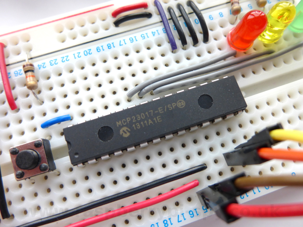
      MCP23017 Example Circuit

      How To Use A MCP23017 I2C Port Expander With The Raspberry Pi – Part 2

      7
      By Matt on July 31, 2013 I2C, Tutorials & Help

      In How To Use A MCP23017 I2C Port Expander With The Raspberry Pi – Part 1 I explained how to configure your Pi to use I2C so you could connect an MCP23017 16-bit port expander to it. If you’ve followed that article and got your circuit ready you are only a few steps away from controlling the chip using a simple Python script.
      MCP23017 Example Circuit

      In this post we will concentrate on controlling outputs. We are using the first three pins of the “GPA” set. There are another set of eight pins (GPB0 – GPB7) which can be controlled in the same way with a few code tweaks.

      For this sort of project a calculator that can convert between binary, decimal and hex is extremely useful. There are plenty of calculators that can do this available for your operating system, whether you are using a desktop or mobile computer. An easy to use binary convertor can be found over at our sister site.

      Python Script For Outputs

      Here is an example script which will count from 1 to 8 setting the first three GPA pins as it goes :

      import smbus
      import time
      
      #bus = smbus.SMBus(0)  # Rev 1 Pi uses 0
      bus = smbus.SMBus(1) # Rev 2 Pi uses 1
      
      DEVICE = 0x20 # Device address (A0-A2)
      IODIRA = 0x00 # Pin direction register
      OLATA  = 0x14 # Register for outputs
      GPIOA  = 0x12 # Register for inputs
      
      # Set all GPA pins as outputs by setting
      # all bits of IODIRA register to 0
      bus.write_byte_data(DEVICE,IODIRA,0x00)
      
      # Set output all 7 output bits to 0
      bus.write_byte_data(DEVICE,OLATA,0)
      
      for MyData in range(1,8):
        # Count from 1 to 8 which in binary will count
        # from 001 to 111
        bus.write_byte_data(DEVICE,OLATA,MyData)
        print MyData
        time.sleep(1)
      
      # Set all bits to zero
      bus.write_byte_data(DEVICE,OLATA,0)
      

      You can download direct to your Pi using :

      wget https://bitbucket.org/MattHawkinsUK/rpispy-misc/raw/master/mcp23017/mcp23017_outputs.py

      You can run the script using the following command :

      sudo python mcp23017_outputs.py

      The script above performs the following actions :

      • Imports the smbus and time libraries
      • Creates an smbus object named “bus”
      • Configures some constants
      • Sets all the GPA pins as outputs
      • Sets all the GPA pins to zero
      • Counts from 1 to 8 and sets the GPA pins to the binary equivalent waiting 1 second between each step
      • Finally sets all GPA to zero

      What you should see is the LEDs light up in a binary sequence :

      000,001,010,011,100,101,110,111

      The most important thing to notice is that when sending data to a register you have to set all 8 bits in one go. So to configure all the GPA pins as outputs you send 0000000 to the IODIRA register. To set them all as inputs you need to send 1111111 binary, or 255 decimal or 0xFF hex. To set GPA0-3 as outputs and GPA4-7 as inputs you need to set 1111000 binary, 240 decimal or 0xF0 hex.

      It’s the same story for setting the pins of outputs. If you’ve set the GPA pins as outputs and you want to set GPA1 high and all the other pins low you need to send 00000010 to the OLATA register. If you want to set GPA2 and GPA7 high you would send 10000100.

      Visit the How To Use A MCP23017 I2C Port Expander With The Raspberry Pi – Part 3 page which explains how to configure pins as inputs and read their state.

      Share. Facebook Twitter Pinterest LinkedIn Tumblr Email
      Previous ArticleHow To Use A MCP23017 I2C Port Expander With The Raspberry Pi – Part 1
      Next Article How To Use A MCP23017 I2C Port Expander With The Raspberry Pi – Part 3

      Related Posts

      Disable SSH Password Login on Raspberry Pi

      How to Add a Raspberry Pi Pico Reset Button

      Pi Pico Onboard LED

      7 Comments

      1. Rhys on September 27, 2013 11:00 am

        Hi,

        Thanks for this info, its really useful. Im very new to all this and trying to understand how to enable multiple pins at once. I don’t really understand the binary and how it works in relation to the GPA pins. Any chance you could help me out?

        Reply
        • Geert Vancompernolle on March 21, 2014 6:25 pm

          Binary is just another numeral system, just like the decimal numeral system we all know very well. But instead of using the base 10, we’re using the base 2 for the binary numeral system.

          For the decimal numeral system, we’re having the numbers 0 to 9. For the binary numeral system, we’re only having 0 and 1 (bi = 2).

          If you have a series of 1’s and 0’s, you have to assign them a weight of power x, where x is the position of the 1 in the bit sequence.
          If the bit position contains a 1, then it’s 2^x, if the bit position contains a 0, then it’s 0^x (or simply 0).
          Example: 1001 => 2^3 + 0^2 + 0^1 + 1 => 2^3 + 1 => 8 + 1 => 9.

          Now back to the MCP23017:
          If you want to control the pins through GPA or GPB, you have to represent each pin by a 0 0r a 1, for a maximum of 8 bits per port.
          So, the minimum value you can send to a port is (in binary representation) 00000000 (being 0 decimal), the maximum value is 11111111 (being 255 decimal).
          In the first case, a 0 is sent to all pins, in the second case, a 1 is sent to all pins. The most left bit of the bit sequence, also known as Most Significant Bit or MSB, represents GPA-7 or GPB-7, the most right bit of the bit sequence, also known as Least Significant Bit or LSB, represents GPA-0 or GPB-0.

          It should be clear now that, if I want to set pin GPA-5 to 1 and all the other pins of GPA to 0, I have to send a 00100000b to the device, being 32 decimal (same calculation as I’ve used before).

          Note that GPA-5 is in fact the 6th IO pin of port GPA, since the datasheet starts from GPA-0. Hence, GPA-5 is the 6th bit in the bit sequence, starting from the right (LSB).

          Reply
      2. Tom H on December 20, 2014 9:52 pm

        My understanding was that the GPA would be addressed like “00000001”, “00000010”, “00000100”, “00001000” and so forth, and therefore bit shifting to the left would give you what you need like so;


        for MyData in range(0,8):
        # Count from 1 to 8 which in binary will count
        # from 001 to 111
        bus.write_byte_data(DEVICE,OLATA,1<<MyData)

        Reply
        • Tom H on December 20, 2014 9:54 pm

          Ah, I see! The intention was to light them in binary sequence, rather than one after another. Cheers.

          Reply
      3. Kurt M on December 4, 2017 6:49 am

        Thanks, super helpful info!

        For anyone wanting to use the GPB side, IODIRB = 0x01, OLATB = 0x15, and GPIOB = 0x13.

        Also, I find that using binary instead of hex makes it way more intuitive to read/write the pin values.
        For example, if I set the output pins to 0b11001100, It’s way easier to see what the outputs will be as opposed to writing 0xCC, even though they mean the same thing in python.

        Reply
      4. Benjamin on July 14, 2019 12:22 am

        “To set GPA0-3 as outputs and GPA4-8 as inputs you need to set 1111000 binary, 240 decimal or 0xF0 hex.”

        I think you meant to say: 0-3 as outputs, and 4-7 as inputs
        Either that, or I’m misunderstanding something here.

        Reply
        • Matt on July 14, 2019 7:20 pm

          You are correct. I’ve updated the post.

          Reply
      Leave A Reply Cancel Reply

      This site uses Akismet to reduce spam. Learn how your comment data is processed.

      Recent Posts
      February 16, 2024

      Disable SSH Password Login on Raspberry Pi

      March 13, 2023

      Elecrow Meteor IPS Touchscreen with RGB LEDs

      December 26, 2022

      Pi Pico Pinout Display on the Command Line

      December 23, 2022

      How to Add a Raspberry Pi Pico Reset Button

      November 20, 2022

      Pi Pico Onboard LED

      Categories
      • 1-wire
      • 3D Printing
      • Add-ons
      • BBC Micro:bit
      • BerryClip
      • Books
      • Camera Module
      • Cases
      • Events
      • General
      • Hardware
      • I2C
      • Infographics
      • Interfaces
      • Minecraft
      • Model A+
      • Model B+
      • News
      • Pi Models
      • Pi Pico
      • Pi Zero
      • Power
      • Programming
      • Python
      • Raspberry Pi OS
      • Raspbian
      • RetroGaming
      • Robotics
      • Sensors
      • Software
      • SPI
      • Tutorials & Help
      Tags
      Arduino audio battery berryclip Birthday bluetooth cambridge camera CamJam DigiMakers display games GPIO I2C interface Kickstarter Kodi LCD LED Linux media Minecraft Model A motionEyeOS PCB photography photos Pi-Lite Pi Pico power python Raspberry Jam Raspberry Pi Bootcamp raspbian Retrogaming retroPie screen SD card security sensor SPI SSH temperature ultrasonic video
      Raspberry PI Related
      • Adafruit Blog
      • Average Maker
      • Official RaspBerry Pi Site
      • Raspberry Pi Pod
      • RasPi.tv
      • RaspTut
      • Stuff About Code
      Tech Resources
      • MattsBits – Pi Resources
      • Microbit Spy
      • Technology Spy
      Archives

      Entries RSS | Comments RSS

      This site is not associated with the official Raspberrypi.org site or the Raspberry Pi Foundation. Raspberry Pi is a trademark of the Raspberry Pi Foundation.

      Copyright © 2025 - All Rights Reserved - Matt Hawkins

      About

      Unofficial site devoted to the Raspberry Pi credit card sized computer offering tutorials, guides, resources,scripts and downloads. We hope to help everyone get the most out of their Pi by providing clear, simple articles on configuring, programming and operating it.

      Popular Posts
      September 19, 2014

      Top 5 Reasons The Raspberry Pi Sucks

      July 27, 2012

      16×2 LCD Module Control Using Python

      October 20, 2013

      Analogue Sensors On The Raspberry Pi Using An MCP3008

      Latest Posts
      February 16, 2024

      Disable SSH Password Login on Raspberry Pi

      March 13, 2023

      Elecrow Meteor IPS Touchscreen with RGB LEDs

      December 26, 2022

      Pi Pico Pinout Display on the Command Line

      Mastodon YouTube Instagram Facebook Pinterest RSS

      Entries RSS | Comments RSS

      This site is not associated with the official Raspberrypi.org site or the Raspberry Pi Foundation. Raspberry Pi is a trademark of the Raspberry Pi Foundation.

      Copyright © 2025 - All Rights Reserved - Matt Hawkins

      mastodon.social@RPiSpy

      Type above and press Enter to search. Press Esc to cancel.