
The Raspberry Pi has no built in analogue inputs which means it is a bit of a pain to use many of the available sensors. I wanted to update my garage security system with the ability to use more sensors so I decided to investigate an easy and cheap way to do it. The MCP3008 was the answer.
The MCP3008 is a 10bit 8-channel Analogue-to-digital converter (ADC). It is cheap, easy to connect and doesn’t require any additional components. It uses the SPI bus protocol which is supported by the Pi’s GPIO header.
This article explains how to use an MCP3008 device to provide 8 analogue inputs which you can use with a range of sensors. In the example circuit below I use my MCP3008 to read a temperature and light sensor.
Here are the bits I used :
- Raspberry Pi
- MCP3008 8 channel ADC
- Light dependent resistor (LDR)
- TMP36 temperature sensor
- 10 Kohm resistor
The first step is enabling the SPI interface on the Pi which is usually disabled by default.
Please follow my Enabling The SPI Interface On The Raspberry Pi article to setup SPI and install the SPI Python wrapper.
Circuit
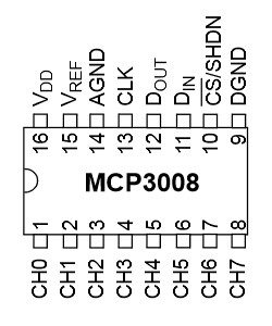
The following list shows how the MCP3008 can be connected. It requires 4 GPIO pins on the Pi P1 Header.
VDD   3.3V
VREF  3.3V
AGND  GROUND
CLK   GPIO11 (P1-23)
DOUT  GPIO9  (P1-21)
DIN   GPIO10 (P1-19)
CS    GPIO8  (P1-24)
DGND  GROUND
The CH0-CH7 pins are the 8 analogue inputs.
Here is my breadboard circuit :
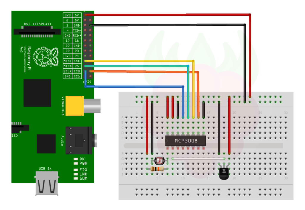 It uses CH0 for the light sensor and CH1 for the TMP36 temperature sensor. The other 6 inputs are spare.
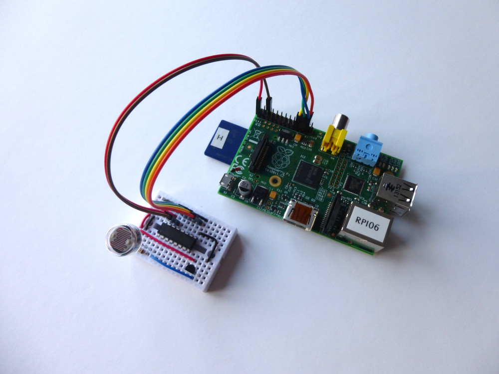
Here is a photo of my test circuit on a small piece of breadboard :
 Light Dependent Resistor
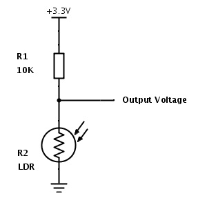
I chose a nice chunky LDR (NORPS-12, datasheet). Under normal lighting its resistance is approximately 10Kohm while in the dark this increases to over 2Mohm.
When there is lots of light the LDR has a low resistance resulting in the output voltage dropping towards 0V.
When it is dark the LDR resistance increases resulting in the output voltage increasing towards 3.3V.
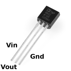 TMP36 Temperature Sensor
The TMP36 temperature sensor is a 3 pin device (datasheet). You can power it with 3.3V and the middle Vout pin will provide a voltage proportional to the temperature.
A temperature of 25 degrees C will result in an output of 0.750V. Each degree results in 10mV of output voltage.
So 0 degrees will give 0.5V and 100 degrees will give 1.5V.
Reading The Data Using a Python Script
The ADC is 10bit so it can report a range of numbers from 0 to 1023 (2 to the power of 10). A reading of 0 means the input is 0V and a reading of 1023 means the input is 3.3V. Our 0-3.3V range would equate to a temperature range of -50 to 280 degrees C using the TMP36.
To read the data I used this Python script :
#!/usr/bin/python

import spidev
import time
import os

# Open SPI bus
spi = spidev.SpiDev()
spi.open(0,0)
spi.max_speed_hz=1000000

# Function to read SPI data from MCP3008 chip
# Channel must be an integer 0-7
def ReadChannel(channel):
  adc = spi.xfer2([1,(8+channel)<<4,0])
  data = ((adc[1]&3) << 8) + adc[2]
  return data

# Function to convert data to voltage level,
# rounded to specified number of decimal places.
def ConvertVolts(data,places):
  volts = (data * 3.3) / float(1023)
  volts = round(volts,places)
  return volts

# Function to calculate temperature from
# TMP36 data, rounded to specified
# number of decimal places.
def ConvertTemp(data,places):

  # ADC Value
  # (approx)  Temp  Volts
  #    0      -50    0.00
  #   78      -25    0.25
  #  155        0    0.50
  #  233       25    0.75
  #  310       50    1.00
  #  465      100    1.50
  #  775      200    2.50
  # 1023      280    3.30

  temp = ((data * 330)/float(1023))-50
  temp = round(temp,places)
  return temp

# Define sensor channels
light_channel = 0
temp_channel  = 1

# Define delay between readings
delay = 5

while True:

  # Read the light sensor data
  light_level = ReadChannel(light_channel)
  light_volts = ConvertVolts(light_level,2)

  # Read the temperature sensor data
  temp_level = ReadChannel(temp_channel)
  temp_volts = ConvertVolts(temp_level,2)
  temp       = ConvertTemp(temp_level,2)

  # Print out results
  print "--------------------------------------------"
  print("Light: {} ({}V)".format(light_level,light_volts))
  print("Temp : {} ({}V) {} deg C".format(temp_level,temp_volts,temp))

  # Wait before repeating loop
  time.sleep(delay)
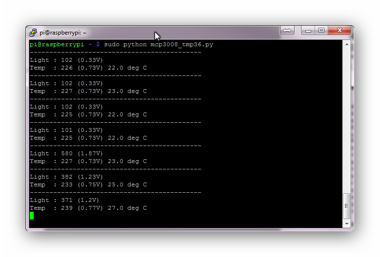
Here is a screen-shot of the output :
You can download this script directly to your Pi using :
wget https://bitbucket.org/MattHawkinsUK/rpispy-misc/raw/master/mcp3008/mcp3008_tmp36.py
It can then be run using :
sudo python mcp3008_tmp36.py
Alternatively if you are a Git fan you can clone my Raspberry Pi misc scripts repo using :
git clone https://bitbucket.org/MattHawkinsUK/rpispy-misc.git
Additional Explanation of spi.xfer2
Lots of people have asked about the spi.xfer2 line. This sends 3 bytes to the device. The first byte is 1 which is equal to 00000001 in binary.
“8+channel” is 00001000 in binary (where channel is 0). “<<4” shifts those bits to the left which gives 10000000. The last byte is 0 which is 00000000 in binary.
So “spi.xfer2([1,(8+channel)<<4,0])” sends 00000001 10000000 00000000 to the device. The device then sends back 3 bytes in response. The “data=” line extracts 10 bits from that response and this represents the measurement.
The exact reason why you do the above is explained in the datasheet but that is outside the scope of this article.
More Information
If you want more technical information about the device please take a look at the official Microchip MCP3008 datasheet. If you want to know more about the SPI bus then take a look at the Serial Peripheral Interface Bus Wikipedia page.
100 Comments
Great guide – thanks for keeping it simple. 🙂
Great article that addresses one of the Pi’s main shortcomings.
Why do people settle for 10 bits with the MCP3008 when the MCP3208 costs pennies more and does 12 bits? I believe it’s pin and code compatible as well. You might as well go for all the resolution available…admittedly it’s up to the user to analogue filter the input to really make good use of the available resolution.
Analog filtering’d work, but cheaper to average the incoming voltage in software.
Thinking of my days with early Nicolet spectrum analysers, we got an extra ½ bit rersolution by adding a bit’s-worth of noise to the analog input. We had to filter first (anti-aliasing – Nyquist and all that…) but in the temp. measurement aliasing isn’t an issue, so any ‘noise’ might actually be beneficial, if averaged over, say 4 samples before presentation…then adjust the resolution in the ‘places’ variable. Worth trying, YMMV.
Quick question: do you know how the data= line would change for the 3208 (which has 12 bits instead of 10?)
Yes, Analogue filtering depends on your application…if all you’r doing is monitoring an essentially static voltage then software filtering is fine for removing the residual noise ….if you’re looking at a signal with a known AC content then you need to worry about Nyquist sampling rates and anti-aliasing.
Dithering is an old trick with lower resolution converters; beyond 12 bits you generally get it for free, especially with breadboard layouts.
I’d like to see a full-blown datalogger done with the Raspberry Pi. Adafruit sell a 16 bit 4 channel ADC assembled on to a small pcb; four of those taken with a RTC chip would make a very useful 16 channel datalogger which could be run off a 12v battery, reasonably low power and no moving parts (fans, disc drives etc), and wouldn’t tie up a PC. I keep planning to do it myself but never get around to it…..
RL
I know this post is pretty old, but I’m building a datalogger from a raspberry pi right now. I was using the 3008, but the COTS data logger I’m trying to knock-off had better resolution than my Pi, so I’m trying to adapt the code and switch to the 3208 right now.
I try to keep this post updated as it’s quite popular. Hopefully it will still be useful in your project. Let me know if you hit any issues.
If i was to follow this project, would it be recommended that i use the exact same LDR and ADC? Thanks for any help, great article!
You could use any LDR. The article deals specifically with the MCP3008 ADC but you could use another … but it would need to be pin compatible and also use the SPI protocol.
Hi Matt,
I just tried this with a different LDR, a TEPT5700 Vishay Photodiode, and an IR photodiode.
For each I used the same circuitry and resistor (10K Ohm) and the results were very much the same.
The fun begins….
Cool! I modified your script and now I can use a potentiometer to “tune” my RaspRadio …
http://mightyohm.com/forum/viewtopic.php?f=2&t=3420
Thank’s a lot!
Schwabinger
Hey what could the problem be if the SPI is only read once in a while…
It’s always 0 and then suddenly shows the correct value and then 0 again?
Thanks Matt
Hi,
Just wanted to say thanks for posting this.
Just been and bought one and some ir led + ir photodiodes.
I’ve previously set up a way to pass morse code from one RPi to another so this would be an ace way to try that out with light.
George
Hi,
in my radio project I now use your solution to control two pots (volume, select station) and two push buttons (signal station number, initiate shutdown/reboot).
http://www.flickr.com/photos/rigasw/sets/72157638612312533/
Do you know whether it does work as well with Pi Version A?
Schwabinger
I can’t see why it wouldn’t work with the Model A. The GPIO pins are the same so should be identical to the Model B as far as the MCP3008 is concerned.
Hi,
thanks for your answer. As I am trying to make my web-radio solar/battery powered, I will get an A model. They are supposed to draw only about 1/3 of energy compared to model B.
The one existing usb-port will be used for a wlan-adapter.
Schwabinger
When I did my AA battery tests the power consumption of the Model A was indeed about 1/3 of the Model B. I usually develop on a Model B and then move the card to the Model A when I don’t need the network socket any more.
Hi,
Thank you for this extensive and very clear explanation. It’s very helpful for a newbie like me.
Ton
For those of us trying to get to grips with both the Spi interface any Python, could you explain how the bits in the brackets on the two lines calling the spi.xfer2 function and organising the data actually work?:
adc = spi.xfer2([1,(8+channel)<<4,0])
data = ((adc[1]&3) << 8) + adc[2]
The datasheet is pretty complex from a standing start!
Regards,
Barney Ward
I too could benefit from a brief breakdown of these lines.
Actually I found a great video that explains it:
http://m.youtube.com/watch?v=oW0mTwFck_c&feature=g-high-rec
That video does explain the numbers quite nicely. Here is a link to the specific point where he explains the 3 bytes :
http://youtu.be/oW0mTwFck_c?t=31m
Hi,
thanks for this post, it’s really interesting!
But I have one doubt.
Is it possible to use the MCP3008 and the RPi to monitor a 12V battery voltage?
And use, for example, a temperature sensor / LDR along with the monitoring of the 12V battery voltage within the same MCP3008?
How the connections would be for this?
I would like to manage some renewable energy with the pi (I’m doing it now with a 12F675 ), but in this case I don’ know how, as I need the ground and positive from the battery, and read the MCP with the Pi :/
Thanks in advance.
I’m sure you could monitor a 0-12V level but you would need to scale the 12V maximum to 3.3V. Perhaps using a simple resistor divider? The MCP3008 has got 8 input channels so you could monitor voltage and a light sensor at the same time.
I’m following this tutorial and only using a photocell. I’ve eliminated the temperature sensor.
When I run the python code in idle I always get the same data back
adc [0 , 3, 255]
volt 3.3v
Light 1023
No matter what I do, I can’t seem to figure out what my problem is.
The photocell I have has been tested and it works.
I’ve tried different channels on the mcp3008 and give the same readings.
My next test is going to be with a potentiometer to see if I can get readings from it.
Any help would be greatly appreciated.
Thanks,
George
I would use a potentiometer to feed 0V – 3.3V to an input and see what result that gives.
I just tried this and the voltage stays at 3.3v
When I test the Ohms on the pot it comes back with varying resistance like it should.
This however is not reflected when it is hooked up to the pi.
Any other thoughts?
Hi George,
I have a similar issue with my setup. 1023 is the constant value I get , don’t know why doesn’t it change. Could you help me do the troubleshooting if you know how to solve the issue now?? Thanks in advance.
Thanks once again for the tutorial. im using it to re-tool the Picorder. 🙂
My Full Sized breadboard is actually split in two. I was running 3v on one half and not the other. So the chip was never getting power.
Rookie mistake….
Hi. An excelllent tutorial.
I am only using the temperature part, so have commented out the lines for the light sensor. Everything works fine, but I have two issues:
1 – The temperature only ever reads in full degrees, even though it’s presented to one decimal place. Am I missing something really obvious? I’d really like to get a more detailed temperature reading.
2 – I have the tmp36 on about 1m of cable (spare piece of cat5). It seems to be reading 4 to 5 degrees below the known temperature. Presumably the length of cable could be the issue here (I’ve tried two different types of cable with roughly the same result). How would I go about some kind of correction for this?
I’m hoping these are really simple things that a noob like me has just not seen. I’d really, really appreciate any pointers in the right direction.
Thanks,
Steve.
Hi Steve,
You spotted a bug. When dividing by an integer (1023) it forces the output to be an integer. So it loses the decimal points in the calculation. I have wrapped the 1023 value in “float” which now retains the decimal places. These are then rounded to 2 decimal places.
As for the accuracy I’m not sure as I haven’t used the sensor on a long cable. It could be due to interference on the wire? What if you try a shorter length?
Excellent and well written tutorial, thanks Matt for your time and effort in making this an easy task for the rest of us. I’ve played with the temperature sensor and also have a similar offset. Yet when checking the output from the sensor the voltage is correct to the temperature. A quick bit of googling has lead me to believe that this may be due to the input impedance of the MCP3008 and that some other simple circuitry may be needed to boost the signal from the sensor.
Me to, a capacitor between Vin and Vout on TMP36 solved the offset problem for me.
Hi Ulf. Thanks for this suggestion. I was slowly coming to the conclusion that there might be interference due to length of wire, in my case about 5m. With zero wire length I was, even then, reading about 5C out. With this long wire it is -25C out! If interference is the factor what value of capacitor across Vin and Vout do you suggest? (Do Vin and Vout equate to Din and Dout?)Thanks, Clive.
Hi Matt,
Thanks for the quick reply.
That all makes sense. I have wrapped the 1023 division with float and now it returns the temperature to two decimal places (just like I’d hope it would). That’s brilliant!
I’ll experiment with putting the tmp36 directly into the breadboard vs using a length of wire. Annoyingly, I’ve sealed the tmp36 in multiple layers of heat-shrink to make it waterproof. I know I could have used a DS18B20 (which I have one of), but I’ve got another project running on GPIO4 which the 1-wire interface needs to use. Plus I wanted to learn how to use the mcp3008.
Slowly but surely, it’s all coming together nicely 🙂
Thanks,
Steve.
Hi there,
I just have a quick question. I am trying to figure out how to amend the “xfer2” and “data =” if I am using the 8-channel 12-bit MCP3208?
Thank you for your help!
Roman
I think the data line would become :
data = ((adc[1]&15) << 8) + adc[2]If your received data is : XXXXXXXX XXXXDDDD ddddddddIt grabs the first 4 bits of the second byte (DDDD), shifts them 8 to the left (to give (DDDD0000). It then adds on the third byte to give DDDDdddddddd. That's your 12 bits.In the calculation to convert the data value into volts you should use 4095 (2^12) rather than 1023 (2^10).I haven't tried this as I don't have an MCP3208 but I think it looks right 🙂
Found out what happens if you wire it up wrong. Chip = Radiator 😀
I’ve got a few I keep spare in case my central heating breaks down.
Hey
I’m a newbie to raspberry pi and python but I would like to create a project with analog inputs, but I would like them to display real-time in a graph, could anyone give me some help with the code/ other examples of this?
Thanks a lot
PS: You created a really good guide that already helped me a lot 😀
Simon
Hi Matt,
Wonderful post. I am trying to do the very same thing on my Beaglebone Black. Yes I know that the Black has endless Analog IOs but I’m using the MCP3008 as protection, seeing that the BBB could only take 1.8 volt.
This is my code so far:
import Adafruit_BBIO.SPI, time, os
spi = Adafruit_BBIO.SPI.SPI()
spi.open (0,0)
def ReadChannel(channel):
adc = spi.xfer2([1,(8+channel)<<4,0]) #
data = ((adc[1]&3) << 8) + adc[2]
return data
the rest is the same as yours from here on.
The problem is I keep getting this error message when I run my program.
*** glibc detected *** python: double free or corruption (fasttop): 0x0008fbb0 ***
Can you shed some light? Thanks in advance.
Richard, did you ever get this to work? Trying to do same thing on BeagleBone Black with MCP3008.
Hi, i’m tryng to misure light but, how could R impact over V in that circuit? V is always 3.3V, because resistance is changing with current so… V is the same 3.3V. Am i wrong?
It forms a voltage divider. If the LDR is 10K then the voltage at the ADC input is 1.65V. If the LDR is a large resistance the voltage is closer to 3.3V. If the LDR is very small the voltage will tend to 0V. So as the resistance changes the voltage will vary between 3.3V and 0V.
A few people have asked about the code changes for an MCP3208. You have to change four lines. The first is to send the data earlier to allow time for the greater number of bits in the response:
adc = spi.xfer2([6+((4&channel)>>2),(3&channel)<<6,0])
You then have to include the extra bits when calculating the output:
data = ((adc[1]&15) << 8) + adc[2]
Finally you have to cope with the extra bits when converting to voltages and temperatures:
volts = (data * 3.3) / float(4095)
temp = ((data * 330)/float(4095))-50
My complete code is available at http://www.jseddon.co.uk/mcp3208_jon.py
Thanks for a great tutorial – that saved me loads of time.
Hi, great post, I’ve eventually got mine working thanks to this guide!! :0)
Just now want to link this to a GUI, ie Glade or WebIOPi.
Do you, or anyone have any examples of doing this?? I’ve been trying for ages but getting no where. Just basically see a value – temperature in a text box……..??
Matt,
This is a very well written and useful post. I needed to create the exact circuit and your guide helped me get it right.
Thanks for taking the time to publish this so others like me can really understand what is going on when requiring ADC tools.
Sopwith
This has stopped working after an RPi firmware update. (It installed today as part of a Raspbian Jessie aptitude update; aptitude upgrade.) Something is wrong with the /dev/spidevx.x devices after that upgrade.
My solution was to go back to an older kernel/firmware.
The last working one can be installed by using this:
rpi-update f74b92120e0d469fc5c2dc85b2b5718d877e1cbb
gives me: uname -a
Linux raspberrypi 3.12.36+ #737 PREEMPT Wed Jan 14 19:40:07 GMT 2015 armv6l GNU/Linux
If anyone knows how this can be made to work in a recent (Raspberry Pi 2 -Ready) Raspbian, please post here and/or amend the blog.
Cheers,
Max
I’ve just updated my SPI setup article and appears to work ok now with the latest version of Raspbian. the SPI Python wrapper has been updated and there is a new technique for enabling the SPI kernel module.
Hi,
Here is an comparison between a temperature sensor using the MCP3008 with a TMP36 and the DS18B20 using the A-wire bus : http://www.magdiblog.fr/gpio/gpio-capteurs-de-temperature/
Nice tutorial, though when I run this code on my pi, the spi.xfer2 line gives me an ‘invalid syntax’ error. Could someone please tell me what I’m doing wrong?
PS- It seems like I have the spidev module installed
Thanks in advance
Hi!
Great tutorial, very clear explanation!
I want to measure temperature sensors in a car. These sensors ground to the car, so they have only one connector. And they are normally used with 12V.
Could I use this chip to measure these sensors with a Raspberry Pi?
Greetings,
Gerrelt.
excuse me this SyntaxError: Non-ASCII character ‘\xf3’Error appears not know how to fix
Did you use wget to grab the text file from Bitbucket or did you copy and paste from the webpage? If you copy and paste it sometimes converts spaces into strange ASCII characters.
Could you please explain why you have connected Vdd and Vref to the same input? I am using an AD22100. It takes a 5V input. Does that mean that I will have to use 5V for Vref in the circuit instead of the 3.3 V? And mainly, can I use 2 different rails for dictating 3.3V in the A/D converter and 5 V for the sensor and the Vref?
Thanks.
Vref sets the voltage range of the inputs so I connected to 3.3V. Vdd is the supply voltage and the MCP3008 runs off 3.3V so I connected it to the same pin. If you are using a Pi you do not want to ever put 5V on the Pi’s GPIO pins. If you power it from 5V and use 5V for Vref I think that would result in 5V outputs. Which is bad. So I would run it off 3.3V. You could assume that if you aren’t going to exceed 85 degrees your sensor will never exceed 3.3V anyway.
Not sure if this is safe but I was playing with an analog feedback servo which (I think) returns a voltage between 0 and 5V (since I was driving the servo with a 5 V power supply). The feedback voltage gives you the position of the servo. I simply connected the feedback lead to the MCP3008. Since I wasn’t sure what to do with the Vref, I kept it on the 3.3V rail (same as Vdd). It seemed to work just fine. I had two feedback servos hooked up and I calibrated the MCP3008 reading to the position of one of them. Then I could use that reading and mirror the position onto the second servo. I thought it was pretty slick. I’m a newbie so take that fact as a disclaimer.
I am just getting started. Could you post a video on how to wire the raspberry pi to the MCP3008. I am a newbie on this.
Disregard my last comment. it worked. I was using an IDE cable. but went for the straight connectors. Perfect thank you !
How can I output this to a google docs sheet ?
Thanks !
I want to use the MCP3008 but I’m having trouble installing SPI for python 3 onto a Raspberry A+. I’ve gone through the raspi-config and SPI appears to be enabled but after I install the SPI wrapper, my python program does not seem to be able of find it.
I am using idle3 because I like the interface. Since the GPIO operations need to be done w/ root privileges, I use the terminal and “sudo idle3” to launch idle3. That’s been working well for me until now.
I found another tutorial that shows how to use the MCP3008 on the generic GPIO pins and got it working just fine. But I would like to learn more about SPI so came here.
Any help would be much appreciated. Thanks.
I figured it out…..
On a whim (and out of frustration), I changed:
sudo apt-get install python2.7-dev
to
sudo apt-get install python3.2-dev
and
sudo python setup.py install
to
sudo python3 setup.py install
Now it’s working. So if anyone else has this problem, try that.
what if i want to use raspberry pi to display an analog signal with a frequency higher than 1Mhz , mcp3008 can do that job ? or it will be very slow display . what is the best alternatives to use , i mean the ADC .
To be honest the Pi probably isn’t the best choice to measure such a signal. You would have to take accurate measurements at 2MHz+.
Hi,
thanks for this nice tutorial.
For my current application I need to read out two ADCs simultaneously, so I got two MCP3008, one connected to CE0 the other to CE1. Using the spi.open(0,x) command I can address either of them. But how can I read out both of them?
Checking out the xfer-protocol, it seems there is no address included. Does that mean I have to open and close the spi-connection after reading out either MCP in order to switch to the other one? That seems rather stupid for a bus protocol but I couldn’t come with a working solution yet.
Any suggestions on how to do that?
Hello,
When I try to use your code, I ve got this error meassage :
TypeError: Argument must be a list of at least one, but not more than 4096
I don’t understand why?
Do you know how to correct this error ?
Thanks,
Mat
What line of the code is the error appearing on?
Hello I am also getting the same error with MAT. Everythin is the same with you bu getting TypeError: Argument must be a list of at least one, but not more than 4096 in the line adc=spi.xfer2([1,(8 + channel)<<4,0]). Read channel function does not work. How can we fix it? Thank you
Want to say “thank you” for posting this explanation and example. Helped me a lot on my project.
I’m using MCP3008 to interface to the Raspberry Pi. The MCP Vdd is 3.3V and from the same source as Raspberry Pi. One of the analog inputs to the MCP is from a instrumentation amp (opamp) AD620. I’ve found for my circuit, operating the AD620 (using to interface to load cell) from a 5V works better than from a 3.3V. The analog input swing from the AD620 to the input of MCP3008 is 3.6V max. So to summarize, I’m operating the MCP3008 from 3.3V and one of the analog can reach a max of 3.6V.
Question:
1 – Its is safe and going to damage my MCP3008. I’ve gone thru the data sheet and believe it should be safe as MCP3008 operating voltage ranges from 2.7V – 5.0V
2- I’m interfacing the MCP3008 to Raspberry using SPI’s DIN and DOUT pins. Assuming the circuitry inside of the MCP3008 is separate between analog and digital, I would think the DOUT pin on the MCP will not exceed the max of the Raspberry and damage it.
Any help would be appreciated.
I think although the voltage range is 2.7-5.0V that is only if it powered with 5V. Even if it worked I suspect it wouldn’t be able to correctly deal with the 3.6V as it would be above the supply voltage. I would add a basic resistor divider to scale the incominbg 3.6V to 3.3V.
hi,
how can you make the program read more than one channel of the mcp3008??
thanks for guide. I am using LM35 temperature sensor and mcp3008 . I am getting continuous value as 3.3 volts and temp 280 C. Can you please help might be the problem.
Disconnect the sensor and double-check the MCP3008 is working and giving sensible values when you apply 0V and 3.3V to the inputs.
Hi Matt
I have replicated this project but it is not working for me. I have followed every instruction and after I compile from the terminal it shows nothing…
thankx o lot for this article it help me
why are you dividing by 1023 instead of 1024? check this out: http://www.mathworks.com/help/supportpkg/raspberrypiio/examples/analog-input-using-spi.html?requestedDomain=www.mathworks.com
I think that Mathworks page is wrong. By their own admission 0=0V and 1023=3.3V. So each unit is equal to 3.3/1023.
A reading of 0000 (lowest) is 0x(3.3/1023)=0V
A reading of 1023 (highest) is 1023x(3.3/1023)=3.3V
Using their code when get the maximum reading of 1023 the voltage is calculated as 1023x(3.3/1024)=3.297V.
Imagine the range is 0-3 rather than the MCP’s 0-1023. 0000=0V and 0003=3.3V. You would divide by 3. Each unit would represent 1.1.
0000=0x1.1=0V
0001=1×1.1=1.1V
0002=2×1.1=2.2V
0003=2×1.1=3.3V
You divide your maximum voltage by the maximum value not the total number of values.
Thanks for your reply. That make sense 🙂
This is great im working on a data logger for my Brothers racecar, was, how would i add a second 3208? using both spi channels to this code?
How to check MCP 3008 working or not.because all the time i am getting ldr value as 0
Apply 3.3V to one of the inputs and see if that gives you a reading on the MCP3008.
The “Additional Explanation of spi.xfer2” part guide me to the MCP3008 datasheet, and I could clearly know what’s going on in the “ReadChannel” function after I saw the FIGURE 6-1 in the datasheet.
This article is the most approachable tutorial that I’ve searched on Google.
Thanks a lot !
Thank you for this very detailed and clear tutorial. I tried with a raspberry pi 3, and it works perfectly.
How do I save the data to a file?
Hi Matt thanks for your tutorial.
I am using MCP3008 with Raspberry pi and an analog vibration sensor. i wire up all the cables as you depict in your project but when i run the code i am just getting the values in the range of 500-550. Interesting thing is: when i touch the sensor, the voltage should increase, but it doesnt. I mean it remains same, whether i touch or not. I am using CH0 for getting the voltage, but , when i play with the sensor, the CH1 values are changing ? Is it weird ? Is it possible to get the values from CH1, while the sensor is wired CHO ?
It depends on what voltage range the vibration sensor outputs. The MCP3008 will measure a 0-3.3V range. What is the range from the sensor? If you have nothing connected to the other channels ignore them. They will just be measuring random noise/interference. Tie them to ground and they will read 0.
Hai Matt thanks for the tutorial
how to use mcp3008 and & LDR to get the value light intensity in lux ?
This works relatively well for me. its probly not 100% accurate but for my purpose its fine.
# Function to approx LUX with 10k ldr & 10k pull up @ 3.3v
# data is the value from the mcp3008
def ConvertLux(data,places):
result = data
vin = 3.3
vout = float(result)/1023 * vin
resOut = 10000/((vin/vout)-1)
resOut = float(5e9) * (math.log10(resOut)**-12.78)
resOut = float(“%.2f” % resOut)
return resOut
Hi Husen! Could you find out how to get the value light intensity in lux? I’m working on a project that has a lot to do with this one and it would be very useful for me to show it in lux, thanks!!
I think the only way to get a reading in LUX is to a) use a sensor that has been calibrated to give a known value for a known LUX level or b) use a light meter to measure what values your sensor gives at set LUX levels.
Thank you very much for this post. Ive just made one using a Pi3 for logging voltage on a piece of equipment in our lab, to check for drift over many days. I modified the code to save data as a txt file as it acquires — a trivial python add-on. Also modified the Pi3 to bootup and start the script directly, so no need for a keyboard or monitor. Your build as described here worked perfectly on the first try, and gave a high level of detail that was easily replicated. Again, thank you for this very helpful project tip.
Hi! Great tutorial, thx for that!
There’s a little error in the calculation, though: You’d need to divide by 1024, not by 1023 (resp. 4096 if using a MCP3208)
There is a debate over this. I think it is be 1023. 0V gives a reading of 0. 5V gives a reading of 1023. When feed in a pure 5V you get a reading of 1023. You would then multiplying by (5/1024) which gives you a voltage of 4.995 not 5V. Dividing by 1023 gives you 5V.
what is the input given to the CLK pin of the IC
It was never mentioned in the code
The CLK pin is part of the SPI interface. So it is controlled by the SPI library so you won’t see any reference to it in my code.
I tried to follow along on my own Pi, but when I started entering your python code into IDLE, I got as far as “import spidev”, and got an error stating that no such library was available to be imported. How do I get that library and add it to my Pi so that I can resume learning what this tutorial has to teach?
You need to follow the link at the beginning to the “Enable SPI interface” tutorial. This includes a step on installing the spidev library.
Thank you. After many attempts with other websites over a few years your line for the Python Spi wrapper in the “Enable SPI interface” tutorial finally allowed me to install “spidev” correctly:
sudo apt-get install python3-spidev python-spidev
Without it “import spidev” always caused a fault! I have no idea yet where the 2 modules are stored but, with that line & your Python code on this page, the Spi & Mcp3008 are communicating.