
 While searching for a simple way to measure temperature using my Raspberry Pi I came across the DS18B20 1-wire digital temperature sensor. This promised an accurate way of measuring temperature with a few wires and almost no external components.
The device only cost a few pounds and it seemed too good to be true …
So I bought one. Within a few minutes I was measuring the temperature with it. It is so simple to use and the perfect starting point for creating a Raspberry Pi based temperature data logger.
 DS18B20 Temperature Sensor

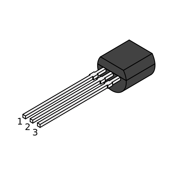
The diagram on the right shows the DS18B20 device. It has three pins and comes in a TO-92 package which means it looks similar to other devices you may have used such as transistors.
Pin 1 is Ground. Pin 2 is the data pin and Pin 3 is the power pin. The only external component required is a single 4.7Kohm resistor.
In my testing I didn’t have one of these so I used 2 x 2.2Kohm resistors in series. This worked fine.
Hardware Setup
I used a small piece of breadboard and some jumper cables to connect it to the GPIO header on my Raspberry Pi.

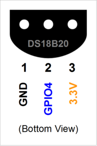
- Sensor Pin 1 connected to P1-06 (Ground)
- Sensor Pin 2 connected to P1-07 (GPIO4)
- Sensor Pin 3 connected to P1-01 (3.3V)
A 4.7Kohm resistor was placed between Sensor pin 2 and 3.
Double check that you don’t confuse Pin 1 and Pin 3 on the device otherwise the power will be applied the wrong way round!
Once you have connected everything together you can power up your Raspberry Pi.
Update Raspbian
It’s always best to tackle new projects with an updated SD card. I tend to use the latest Raspbian image from the RaspberryPi.org download page and then update it from time to time using the following two commands :
sudo apt-get update
sudo apt-get upgrade
Enable 1-Wire Interface
The DS18B20 sensor uses the 1-Wire protocol. This needs to be enabled so either follow the instructions below or refer to the Enable 1-Wire Interface on the Raspberry Pi post.
In order to enable the 1-Wire interface you just need to make a small change to the config.txt file using :
sudo nano /boot/config.txt
add the following line to the bottom :
dtoverlay=w1-gpio,gpiopin=4
You can save the file using CTRL-X, Y then RETURN. The device is setup to report its temperature via GPIO4.
For the changes to take effect you will need to reboot using :
sudo reboot
Check for Connected Devices
Use the commands below to go to the directory that contains the detected 1-wire devices :
cd /sys/bus/w1/devices
ls
This will list the directories associated with your 1-wire devices.
Get Sensor ID
Each sensor has a unique ID and in my case it is 28-00000482b243. Your ID will be different so be sure to use that in the example code below.
Read Temperature
Using “cd” we can change to the temperature sensor directory, list the contents and then view the “w1_slave” file :
cd 28-00000482b243
ls
cat w1_slave
The complete command line setup process looks like this :
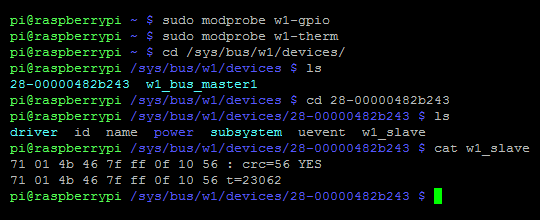
The “w1_slave” file contains a bunch of data but the “t=23062” at the end is the temperature reading. In this example the temperature is 23.062 degrees Celsius (centigrade).
Try touching the sensor with your finger and then using “cat w1_slave” to take another reading …
In order to read the temperature via Python here is a basic script :
#!/usr/bin/python
def gettemp(id):
  try:
    mytemp = ''
    filename = 'w1_slave'
    f = open('/sys/bus/w1/devices/' + id + '/' + filename, 'r')
    line = f.readline() # read 1st line
    crc = line.rsplit(' ',1)
    crc = crc[1].replace('\n', '')
    if crc=='YES':
      line = f.readline() # read 2nd line
      mytemp = line.rsplit('t=',1)
    else:
      mytemp = 99999
    f.close()

    return int(mytemp[1])

  except:
    return 99999

if __name__ == '__main__':

  # Script has been called directly
  id = '28-00000482b243'
  print "Temp : " + '{:.3f}'.format(gettemp(id)/float(1000))
This ds18b20.py script can be downloaded directly to your Pi from BitBucket :
wget https://bitbucket.org/MattHawkinsUK/rpispy-misc/raw/master/python/ds18b20.py
and then run using :
python ds18b20.py
Note : You will need to replace my reference to 28-00000482b243 with the id of your device.
Troubleshooting
- Are you using the latest Raspbian image or have you updated your existing image?
- Have you enabled the 1-wire interface?
- Have you correctly wired up the device?
- Did you add the correct sensor ID to the Python script?
52 Comments
I tried this using various tutorials but my Rpi with lastest firmware (rpi-update) is not detecting my DS18B20 sensor, I had a DHT11 which works fine.
Have you tried using Occidentalis?
No I haven’t tried that due to lack of time. Where possible I use the standard Raspbian image as that covers the most users and is always going to reflect the latest developments at the Foundation.
Bought 2 DS18B20 and they work flawlessly, thank you!
Great article Matt. I was thinking about using these sensors to monitor my central heating system, Have you any idea how many of these sensors you can hook up ?
I’d like to use at least 12 sensors to monitor various points in the system, out side temp and room temps. Eventually hooking up some valves and interface to the boiler to automate it all.
Hi.
I use graphite for data logger.
http://hindberid.is/index.php/raspberry-pi
worked flawlessly. Used to monitor my room temp remotely on vacation 🙂
Thank you, I’ve tried it with the DS18D20 in a PCB that I bought on ebay and it works perfect!
Thanks for the write up!
I believe :
Is wrong, and it should actually be P1-01, as this is the 3.3V pin, and that’s actually how you’ve shown it on the diagram.
Well spotted. I have updated the text.
If using a long bus, it’s better to use a 10k resistor to +3,3 volt at both the begin and end of the line, otherwise echo on the line can disturb the communications…
And also use an twisted pair like cat5 cable, I used green/white for data, green for ground (0 volt), brown/white for +3,3 volt, brown for data return.
At the rpi i connected brown with green white to create 1 long path and put the resistors, 1 on the brown and one on the green/white…
Jeroen – how far away was your sensor from your pi? 10′? 20′? 30′?
Also, do you have a quick diagram of what you are describing? I’m having a little trouble visualizing it. Thanks in advance.
I’m using collectd (sudo apt-get install collectd-core) with a perl CGI script (based on collection3 installed by collecd) to export the data via JSON to highcharts javascript library.
http://renarin.zapto.org/wordpress/?p=26 shows my CPU & GPU temps.
Pingback: ใช้ DS18B20 ผ่านทาง 1-Wire เพื่อวัดอุณหภูมิ | Raspberry Pi Thailand
Pingback: LCD display with RPi and room temperature : The Unwritten Words
Hello, I am looking for a way to connect a thermometer in an item in the oven and send me the temps online. Also any idea were to get the probe?
Pingback: Adding the temperature sensor to the Pi | Colin's Arduino, Computer and Electronics Blog
Hi,
i have problem with GPIO4, i think it’s crashed. When I switch to mode out it comes to mode in after few seconds. What do you think?
Is there any possibilities how to use these thermometer by 1W on other port?
Thank you!
hello ive been pouring over the internet trying to find a solution. my pi wont recognize the waterproof DS18B20 at all. could it be faulty? ive tried so many things. changed jumper cables, changed the resister etc.
bookmarked, fantastic site!
stopped working since the sudo apt-get update then upgrade, have they done something to where the devices are now kept?
Try an older ver of build
It’s a bit confusing but try adding the following line to the end of /boot/config.txt :
dtoverlay=w1-gpio,gpiopin=4
I can’t find my sensor so can’t test at the moment.
type: nano /boot/config.txt
Btw thanks for the information, it works now here !
Had the same issue this AM after reboot. Adding
dtoverlay=w1-gpio,gpiopin=4to /boot/config.txt fixed the problem for me.
Thanks!
Thanks, I was worried I broke the sensors, but this worked for me! 3/8/15
hello,
wen i am try to look for the id of my senser.
it won’t give the number but only w1_bus_master1
does somone nows wath i am doing wrong?
i use the TSIC 206/306 as sensor.
Hi Jasper,
your sensor (Tsic) is not supported by the 1wire protcoll. You will need to use the zacwire protocoll in order to read out Tsic sensors.
How do you convert the following print command line so it would work in Python3?
print “Temp : ” + ‘{:.3f}’.format(gettemp(id)/float(1000))
I need to use Python3 and I’m getting a syntax error.
I think you just put brackets around it as print is a function in Python 3 :
print(“Temp : ” + ‘{:.3f}’.format(gettemp(id)/float(1000)))Thanks, Matt! I tried enclosing it in double quotes and single quotes and didn’t try brackets.
It works great! I’m displaying the temp on an I2c lcd and the library only works on Python3.
Short Bus = Networks of less than 1 meter (3 feet).
Long Bus = Anything longer than a short bus.
You can also make VDD = 5V (power it from the 5V pin) and Vpullup = 3.3V. The sensor Data line (DQ) is open-drain so it can only go as high as the Vpullup voltage.
And by the way .. did you know that you can ask MAXIM for a couple of sample sensors?
https://www.maximintegrated.com/en/app-notes/index.mvp/id/148
Please don’t ever type “sudo nano” or “sudo vim” etc.
Always use “sudoedit” instead as this runs in a way that can’t be exploited and makes sure that the file hasn’t been edited under you causing changes to be trampled on.
If you don’t like the editor that sudoedit uses, change your EDITOR variable in your bashrc.
I am guessing the need to put dtoverlay=w1-gpio,gpiopin=4 into /boot/config.txt is due to the introduction of device tree. Have a look at this for more. http://www.raspberrypi.org/documentation/configuration/device-tree.md
Pingback: What is a failproof method for testing a GPIO pin? | DL-UAT
Hi,
I used your code for a quick and dirty systemd (Arch-arm for now) integration with logging to /var/tmp/temp (csv):
https://github.com/UbiCastTeam/rpi-temp-logger
Thanks to systemd, it does print out the current temperature to journalctl:
Mar 10 15:52:53 myhost python[146]: Temp of sensor 28-0414604d6aff : 25.56 C
Mar 10 15:53:24 myhost python[146]: Temp of sensor 28-0414604d6aff : 25.56 C
I hope you don’t mind me reusing your code (i chose a BSD license); please tell if that’s an issue.
You are the best. My ds18b20 works fine.
Thank you. I bookmarked the site.
I have been struggling for a month. Was it my sensors or my pi? So I bought another pi because I could not “see” my sensors. Still not luck. Added the one line of code dtoverlay=w1-gpio,gpiopin=4 there it was. Thanks!!
Sigh – I have a knack of finding problems no-one has published yet.
I have several DS18B20 with either a Raspberry Pi 1B or v2 which insists it constantly 85 C where I am playing. For those that aren’t aware 85 is the default temperature recorded at power up. My problem is that I cannot convince it to change to something realistic.
Since everything I have read does not include explicitly sending a Convert T command, I presume that that is not necessary.
I’m assuming that, I’m missing something really trivial, or something is amiss in the drivers on all of my SD cards and for both versions. Now I’m out of my league – I have no idea where to look and what for.
Anyone got any suggestions ?
cheers
Graham
( New Zealand )
All I can suggest is creating a fresh SD card with the latest Raspbian image, using 1 sensor and following the tutorial. I’m not sure what you mean by a “Convert T command”?
So here’s a very red face | 😉 |
It turns out I failed to notice a pesky little ‘p’ on the end of the part number !! – that makes it parasitic power only, and I haven’t been doing that. 🙁
So in exchange for a couple of days head scratching and cussing – at least I’ve learned what the symptom is for that ‘wrong device’ or ‘incorrectly connected’ scenario.
cheers
Graham.
Hi
I have “pt100” analog temperature sensor ;is it supported by the 1wire protcoll?
Not familiar with the device but seems to be just a resistor that varies with temperature. It has no intelligence doesn’t support the 1-wire protocol.
Pingback: Hooking Up Thermometer to Raspberry Pi (DS18B20) | Pythagoraspberry
Hi
Got GPIO4 occupied by RTC.
Changed to another port and altered command to:
dtoverlay=w1-gpio,gpiopin=24
Works perfect in Python2, not at all in Python3.
Lets go fill the house with temp-sensors 😉
Is anyone familiar with the maximum distance that one can have the sensor away from the pi? I read Jeroen’s post above, but I am wondering if the sensor could be mounted 20 to 50′ away and still provide an accurate reading? Has anyone tested this? Thanks in advance
Use a serial/usb adapter. You can reach 30m (100 ft) with one.
If you have a sensor reading (and not the default 85 deg C) it’s as accurate as it can be.
With the GPIO, in order to have a longer cable .. try lower the resistor value to 2kohm, see what you get.
if you want to use the sensor without having to reboot you can run
sudo modprobe w1-gpio
Hi,
Great article – much appreciated.
I am new and trying to get in to electronics.
How did you know that this requires a 4.7Kohm resistor?
What does the dtoverlay=w1-gpio,gpiopin=4 command do, and is it necessary for newer Pis?
Thanks
The value of the resistor is specified in the datasheet for the DS18B20 (https://datasheets.maximintegrated.com/en/ds/DS18B20.pdf)
The dtoverlay command tells the system you want to use the 1-wire protocol on GPIO4. This required for newer Pis.
Great article…..I want to use two temp sensors on gpio 4 and gpio17
what should my entry in config.txt be?
dtoverlay=w1-gpio,gpiopin=4
Ideally you should connect both sensors to GPIO4. Each one will have its own ID and you can read them independently in your software.