
For all of my projects I have used the standard GPIO header pins as inputs and outputs. This gives you a total of 17 pins to play with but what if you need more?
The easiest way of getting more inputs and outputs is to use an “i/o port expander”. This is a device that allows you to control a number of ports using data you send to the device.
 Other people have has lots of success using I2C devices so I decided to give one a try. I2C is a serial communications protocol which allows chips to swap data on the same “bus”. A port expander takes the data and controls the appropriate pins. This allows lots of sensors and devices to be controlled using only a few of the Pi’s GPIO pins.
The Hardware Set-up
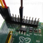
 The device I chose was a MCP23017 I2C port expander with a total of 16 ports. To drive it you use the two I2C pins on the Pi’s GPIO header (Pins 3 and 5). This would give us 31 (15 + 16) inputs or outputs to play with!
It’s actually possible to drive multiple port expanders giving you a huge boost in the number of inputs or outputs available. Adding another MCP23017 would increase the GPIO count from 31 to 47 (15 + 16 + 16). All for a few £/$.
The great thing with these devices is that they are cheap (a couple of £/$) and require very few external components.
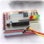
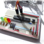
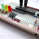
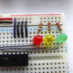
In this example I’ve got 3 LEDs and a push switch connected to the device which is being driven by the two I2C pins on the Pi. I’ve used 330 ohm resistors to limit the current through the LEDs. You can use other suitable values but I tend to use 330 (as I’ve lots of them available due to my BerryClip stock!) :
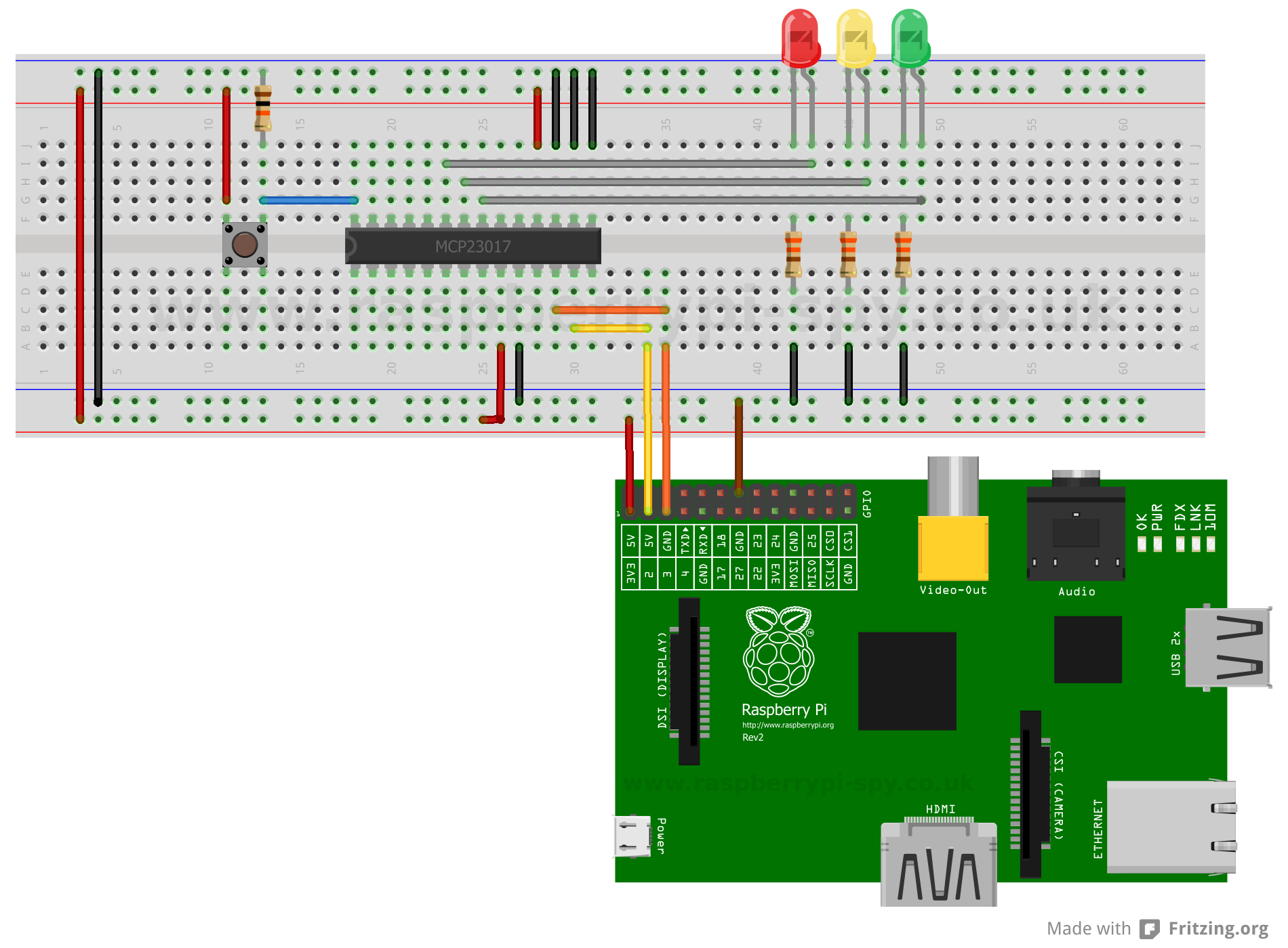 The switch resistor is 10Kohm and ties the input to ground. This insures the input is Low until the switch it pressed. Pressing the switch places 3.3V on the input resulting in it going High. The resistor stops this resulting in a short circuit between the two power rails.
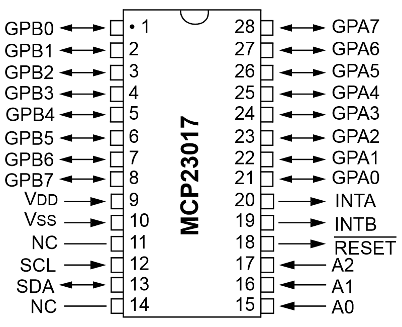
- Pin 9 (VDD) is connected to 3.3V
- Pin 10 (VSS) is connected to Ground
- Pin 12 (SCL) is connected to Pin 5 on the Pi GPIO
- Pin 13 (SDA) is connected to Pin 3 on the Pi GPIO
- Pin 18 (Reset) should be set high for normal operation so we connect this to 3.3V
- Pins 15, 16 & 17 (A0-A2) determine the number assigned to this device. We are only using one device so we will give it a binary zero by setting all three of these pins to 0 (ground)
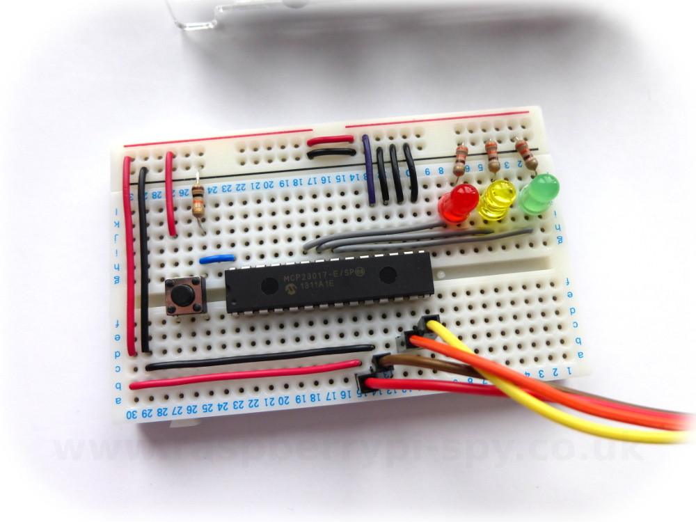
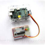
Here is a photo of my test circuit built on a small piece of breadboard :
The System Set-up
To use I2C on the Pi you need to enable a few things in Raspbian as by default it is not enabled. This is a fairly easy process and is described in my Enabling The I2C Interface On The Raspberry Pi tutorial.
Testing The Hardware
Once you’ve enabled you i2c interface and connected your hardware double check the wiring. Make sure 3.3V is going to the correct pins and you’ve got not short circuits. Power up the Pi and wait for it to boot.
If you’ve got a Rev 2 Pi or later then type the following command :
sudo i2cdetect -y 1
If you’ve got an original Rev 1 Pi then type the following command :
sudo i2cdetect -y 0
Why the difference? Between the Rev 1 and Rev 2 versions of the Pi they changed the signals that went to Pin 3 and Pin 5 on the GPIO header. This changed the device number that needs to be used with I2C from 0 to 1.
I used a Rev 1 Pi and my output looked like this :
pi@raspberrypi ~ $ sudo i2cdetect -y 0
     0  1  2  3  4  5  6  7  8  9  a  b  c  d  e  f
00:          -- -- -- -- -- -- -- -- -- -- -- -- --
10: -- -- -- -- -- -- -- -- -- -- -- -- -- -- -- --
20: 20 -- -- -- -- -- -- -- -- -- -- -- -- -- -- --
30: -- -- -- -- -- -- -- -- -- -- -- -- -- -- -- --
40: -- -- -- -- -- -- -- -- -- -- -- -- -- -- -- --
50: -- -- -- -- -- -- -- -- -- -- -- -- -- -- -- --
60: -- -- -- -- -- -- -- -- -- -- -- -- -- -- -- --
70: -- -- -- -- -- -- -- --
This shows that I’ve got one device connected and its address is 0x20 (32 in decimal). This is because the three address pins are set low. If you set A0 high the address would become 0x21 (33 in decimal). How you set A0, A1 and A2 is up to you but all your I2C devices must have a unique address.
Command Line Test
To do a quick test we can use the command line to enable the LED on GPA0 :
First we configure Port A pins GPA0-6 as outputs and GPA7 as an input. (10000000 in binary and 0x80 in hex) :
sudo i2cset -y 1 0x20 0x00 0x80
Then we set GPA0 to logic high which will enable the LED :
sudo i2cset -y 1 0x20 0x14 0x01
To turn off the LED we use :
sudo i2cset -y 1 0x20 0x14 0x00
Remember to replace the 1 with a 0 if you are using a Rev 1 board.
It’s time to start using those extra GPIOs …
Check out How To Use A MCP23017 I2C Port Expander With The Raspberry Pi – Part 2 for instructions on how you can control outputs using Python scripts.
Check out How To Use A MCP23017 I2C Port Expander With The Raspberry Pi – Part 3 for instructions on how you can control inputs using Python scripts.
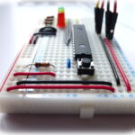
Here are some photos of my test circuit for reference :
27 Comments
Great tutorial, thanks. Presumably this approach also affords some protection against short circuits etc to the gpio pins?
This is great, for those of us with failing eyesite can you give the value of the resistors you used.
Regards
I’ve updated the text. They are 330 ohm. I used them because I’ve a lot of them available but you could use other values if required.
Matt,
Thanks for the fast response, what about the other resistor between the switch and ground (what does this do?) A lot of this is new to me so forgive my questions,
I built a chess computer using an RPI & an Arduino, (www.chess.fortheray.co.uk) I needed the Arduino because of the lack of pins on the PI, but using the port exander should enable me to do it all on the RPI.
Thanks,
Max
The switch resistor is 10Kohm. I’ve updated the text to give a bit more explanation about its purpose. When the switch is not being pressed it connects the input to ground (Low). When the switch is pressed the input sees 3.3V (High). Current flows through the resistor but it is only 3.3/10 mA so nothing noticeable.
Matt,
I have worked my way through all your excellent tutorials and I now think I have all I need for my project. I am building a wooden chess computer that senses moves using 64 reed switches, and signals moves with 64 LEDS. Even with multiplexing I need 24 inputs. see http://www.chess.fortherapy.co.uk .
In my original project I used an Arduino to provide the inputs, communicating serially to the RPI, but now I should be able to do everything on the Pi. Thanks again, Max
Hi,
This is working great for me now. But I can’t figure out how to use the b0-7 pins? Any help?
Many thanks Matt for this clear tutorial. It has given me the confidence to progress my internet radio project to now include many preset swithed stations. One worry is the time it will take to poll all the switched inputs, but I can only try.
Cheers, Timbergetter.
I followed your procedure above. My response to the i2cdetect command is like yours but when I try to turn on the LED connected to gp0 nothing happens (command return code “0”). My wiring diagram is in post 31 at http://dicks-raspberry-pi.blogspot.com/
It doesn’t look like you’ve connected the VDD pin to 3.3V on your diagram.
Matt, is there a ‘mouse-o’ on the circuit picture? On the bottom 5V rail just below the digits ’01’ of the mcp23017 there appears to be an extra horizontal connection.
That’s deliberate. On the breadboard power rails there are gaps so I had to draw a horizontal connection to attach the wire to a hole. I don’t like diagonal lines 🙂
Hi. I’m trying to use the MCP23017 to power a simple segment display (onme pin per segment). Problem is, the segment uses one shared 3.3V connection, and then each segment is controlled by connecting a ground.
For the life of me I can’t work out how to switch on/off a GND connection with this chip – it seems to only support output power via each pin. Any ideas?
great tutorial! I’m gonna try using this to create an oven mapping device (9 temperature probes – each corner plus one centre). I need a lot of pins for resolution in the AtoD conversion. I gather activating each MCP23017 in sequence in the software code will take a sample temperature reading from each probe in turn (though there are only eight addresses available so eight MCP chips/probes?). I’m still very much in the early stages.
The MCP23017 is a port expander so it gives you 8 inputs and outputs. These are just logic levels. It isn’t an ADC so can’t read analogue inputs. It depends on the probes but you should look at my MCP3008 posts. That is an ADC with 8 inputs. You can use two devices to read 16 analogue channels with 10-bit precision.
Hi, Thanks for the reply. I’m really keen for as great an accuracy as i can get (probably +/- 0.25 degC at best if i’m lucky). I’ve been checking out the Maxim31855 (maybe one chip per probe) due to its 14 bit resolution and cold junction compensation. The output is a serial output, I thought I might have to use a multiplexer, but if I can avoid it and sample temperature across all nine points then so much the better?
Hi,
I’m trying to understand the i2cset commands better 🙂
sudo i2cset -y 1 0x20 0x14 0x01
works perfectly – the LED goes on 🙂
the “1” I understand – reference to the bus on the Raspberry Pi.
0x20 is the address of the chip
0x14 -where does this come from? man i2cset says this is the data address – but if I look at the mcp23017 datasheet this seems to be the address for INTCONB. Obviously I don’t understand this as the LED lights up 🙂
0x01 – set pin 0 high
Would love to understand where I’m reading the datasheet wrong 🙂
It’s the address of the output latches. In the datasheet it is “OLATA” and is quoted as 0x14.
Firstly allow me to thank you for this great article.
I’m used to working with Arduino and ussually I have to place 4.7K resistors on SDA and SCL to 5V. Why don’t you do this on a Raspberry Pi? Does it have internal pullup resistors on the SDA and SCL pins?
Unlike the Arduino, the BCM2835 has both pull-up an down internal resistors they have a value of approximately 50KΩ on the Raspberry Pi.
Chek my Python library to control the MCP23017 GPIO. With this library you can use the chip with simple commands.
https://github.com/rpsreal/MCP23017_I2C-with-Raspberry-Pi-.git
Hey, thanks for that greate tutorial! 🙂
Is it possible to add an I/O epander like the MCP23017 to the Pi and connect an ad converter like the MCP3008 to it and attach some sensor to that one?
No idea if that is possible.
If it is, do you, by chance, know how wiring is done in that case?
🙂
Hi i think i am being terribly thick, I have seen in this example how to make the LED light using sudo i2cset -y 1 0x20 0x14 0x01 but how do i amend the code to make the 2nd led light connected to the GPA1 cheers
The three LEDs are connected to GPA1,2 & 3. To light them up you need to think of a 3 digit binary sequence but converted to Hex for the code.
RYG
—–
001 – Green ON
010 – Yellow ON
100 – Red ON
101 – Red and Green ON
So …
Green
sudo i2cset -y 1 0x20 0x14 0x01Yellow
sudo i2cset -y 1 0x20 0x14 0x02Red
sudo i2cset -y 1 0x20 0x14 0x04To light up Green and Red you need 1 + 4 :
sudo i2cset -y 1 0x20 0x14 0x04Yellow and Red is 2 + 4 :
sudo i2cset -y 1 0x20 0x14 0x06thankyou im getting somewhere now
why does this circuit have 3 grounds going into A0, A1 and A2?
why is there a voltage in on RESET?
for a simpler, output only would these be necessary at all?
A0,A1 and A2 are connected to ground to make sure they are set low. If they aren’t connected to something their logic level may “float” and give unpredictable results. The Reset pin is set High for normal operation as defined in the datasheet. When connected High or Low you know what state they are in. If you don’t connect them their state is unknown and unpredictable.