
While browsing eBay looking at electronics stuff I found a few interesting items to connect to the Pi. The first item was a small 2-axis analogue joystick. They are similar to the thumb-sticks you would find on a modern games console controller. These modules are cheap and easy to connect to a circuit so I decided to get one. The outputs are analogue so you need a mechanism for the Pi to read these voltages.
In this post I’ll show how you can you use this device with the Pi. Once working this could be used as an input device for all sorts of projects. Perhaps a Python game written using the Pygame module?
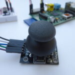
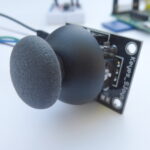
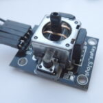
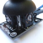 The device I bought was labelled “Keyes_SJoyes”. It consists of two potentiometers which give an analogue voltage based on the horizontal and vertical position of the thumb-stick. Pressing the stick activates a small switch. There are no fancy components on the board and because it is really just two variable resistors works fine with 3.3V despite the 5V PCB label.
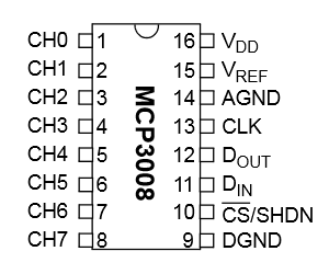 In order to measure the X and Y voltages I decided to use an MCP3008 10 bit Analogue to Digital Converter. These devices are cheap, easy to setup and allow 8 analogue inputs to be read by the Pi using it’s SPI interface. In this tutorial we will only need three of its inputs.
See my previous MCP3008 post for details of how I used one to read light levels and temperature.
Breadboard Circuit
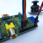
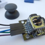
Here is my test circuit. The pin-out of my joystick is slightly different to the Sparkfun symbol I used in this diagram but the wire colour coding matches the photos.
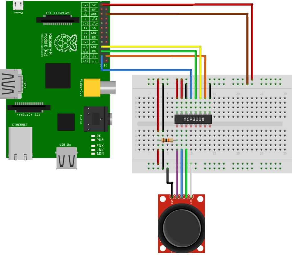
Here is the wiring information for the joystick module :
Joystick          Pi/MCP3008              Wire Colour
--------------    ----------------------  ----------------
GND  (Ground)     Pi GPIO Pin 6 (Ground)  Black
5V   (3.3V)       Pi GPIO Pin 1 (3.3V)    White
SW   (Switch)     MCP3008 Pin 1 (CH0)     Purple
VRx  (X voltage)  MCP3008 Pin 2 (CH1)     Blue
VRy  (Y voltage)  MCP3008 Pin 3 (CH2)     Green
The MCP3008 is wired up just as it was in my previous post :
MCP3008           Pi                      Wire Colour
--------------    ----------------        -----------
Pin 1  (CH0)      -                       Purple
Pin 2  (CH1)      -                       Blue
Pin 3  (CH2)      -                       Green
Pin 9  (DGND)     Pin 6  (Ground)         Black
Pin 10 (CS)       Pin 24 (GPIO8)          Orange
Pin 11 (DIN)      Pin 19 (GPIO10)         Yellow
Pin 12 (DOUT)     Pin 21 (GPIO9)          Green
Pin 13 (CLK)      Pin 23 (GPIO11)         Blue
Pin 14 (AGND)     Pin 6  (Ground)         Black
Pin 15 (VREF)     Pin 1  (3.3V)           Red
Pin 16 (VDD)      Pin 1  (3.3V)           Red
 In this case we are using three of the analogue inputs. You could read the Switch value using a normal GPIO pin but in this case I decided to use an analogue input for convenience.
The 10K resistor is used to pull the switch input High (3.3V). When the switch is pressed the input is connected to ground (0V). Without the resistor the input would be in an undefined state when the switch wasn’t being pressed and read random values. Give it a try.
Pi SPI Configuration
In order to use the MCP3008 we need to configure the SPI bus on the Pi first. Rather than repeat the instructions here open the Analogue Sensors On The Raspberry Pi Using An MCP3008 tutorial in a new browser window and complete the sections :
- Enable Hardware SPI
- Install Python SPI Wrapper
Python Test Script
Hopefully if you’ve wired it up correctly and got the SPI interface configured we are ready to run a Python script to read the joystick values.
The ADC is 10-bit so it can report a range of numbers from 0 to 1023 (2 to the power of 10). A reading of 0 means the input is 0V and a reading of 1023 means the input is 3.3V. In our circuit the switch will read 3.3V (1023) until it is pressed when it will read 0V (0). The X and Y joystick values will vary between 0 and 1023 as they are moved from one extreme to another. In the centre position we would expect a a value of 511.5. In reality this is going to vary between 509 and 514.
#!/usr/bin/python
#--------------------------------------
# This script reads data from a
# MCP3008 ADC device using the SPI bus.
#
# Analogue joystick version!
#
# Author : Matt Hawkins
# Date   : 17/04/2014
#
# https://www.raspberrypi-spy.co.uk/
#
#--------------------------------------

import spidev
import time
import os

# Open SPI bus
spi = spidev.SpiDev()
spi.open(0,0)

# Function to read SPI data from MCP3008 chip
# Channel must be an integer 0-7
def ReadChannel(channel):
  adc = spi.xfer2([1,(8+channel)<<4,0])
  data = ((adc[1]&3) << 8) + adc[2]
  return data

# Define sensor channels
# (channels 3 to 7 unused)
swt_channel = 0
vrx_channel = 1
vry_channel = 2

# Define delay between readings (s)
delay = 0.5

while True:

  # Read the joystick position data
  vrx_pos = ReadChannel(vrx_channel)
  vry_pos = ReadChannel(vry_channel)

  # Read switch state
  swt_val = ReadChannel(swt_channel)

  # Print out results
  print "--------------------------------------------"
  print("X : {}  Y : {}  Switch : {}".format(vrx_pos,vry_pos,swt_val))

  # Wait before repeating loop
  time.sleep(delay)
You can download this script directly to your Pi using :
wget https://bitbucket.org/MattHawkinsUK/rpispy-misc/raw/master/mcp3008/mcp3008_joystick.py
This can then be run using :
sudo python mcp3008_joystick.py
If everything has worked correctly you should see an output that looks something like :
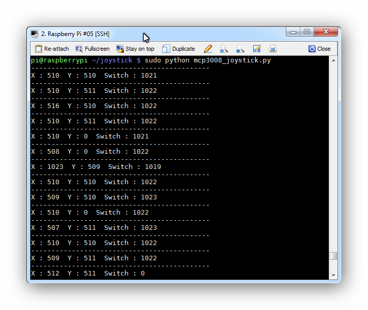
The switch reading varies but is always >1010 when not pressed and <10 when pressed.
As you move the thumb-stick you should see the X and Y values changing. You can reduce the value of the “delay” variable to increase the update rate.
Now that you can read values from a joystick you just need to think of a project to use it in! You could add an additional module and use another three channels on the MCP3008.
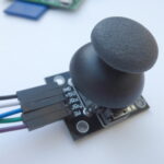
Here are some photos of the test circuit and the thumb-stick joystick module :
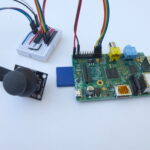
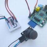
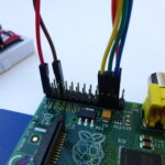
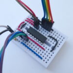
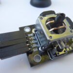
You may notice my breadboard in the photos has a few extra wires on it (long red wire, long blue wire and bent black wire). These were left over from previous MCP3008 tutorials and can be ignored.
Here are some other blog posts I found using an analogue 2-axis joystick with a Raspberry Pi :
http://devilqube.blogspot.co.uk/2014/02/analog-thumbstick-and-raspberry-pi.html
https://learn.adafruit.com/cupcade-raspberry-pi-micro-mini-arcade-game-cabinet
17 Comments
Thank you for this excellent post Matt – I’m trying to learn the MCP3008 to do a bit of a write up myself (going to make my joystick light things up) and this seems to be the first post that has led me to success! Cheers!
Average Man
Hi Matt,
Thanks for providing these details. The images are really helpful as well. I’m hoping to use a joystick like this to control two servos in order to move a camera which will stream to a screen.
Firstly, would it be possible to use this type of input, albeit, with a slightly tailored set up to control servos?
Secondly, and this might be a bit of a novice question, would I still be able to use a mini TFT screen even though some of the GPIO pins are being used to control the servos and the joystick? I’m thinking of a mini touch screen that sits on the GPIO pins.
Thanks,
Chris
Once you read the joystick positions you can use those numbers to drive anything else you can think of. The joystick position range could be mapped to a range of value sent to a servo control system. I’ve not done much with servos and it will depend a lot on what you are using to control them.
Ok, I think I understand the principle. I’ve seen an example of what I want to achieve using an Arduino but I’m not sure I have the same grasp of that controller as I do with the RPi.
Thanks for your response.
Chris
could you connect a second analog stick similarly with same power but using pins 4, 5, and 6 for input?
thanks
Yes that should work fine.
I am getting all 0 when I run the script. I am not sure what is going on I have triple checked all my connections but get the same result. Perhaps I have not installed SPI correctly but I have double checked all that too. Maybe my MCP3008 chip is bad? I don’t know what is going on.
Try it without the joystick and check what values you get with a 0V or 3.3V input. This will at least confirm if the MCP3008 is working.
Possibly but you would need some sort of driver to read the position. I’m not sure how to implement that.
Thanks for the clear tutorial(s) Matt!
I had gotten a set of Arduino sensors awhile back, and just purchased an MCP3008 last week on your recommendation. I was excited to walk through your tuts tonight, and am glad to say the joystick is working great (well, my “resting” position is 532,506 for x and y… I’m assuming my joystick is a little messed up, but that’d be easy to compensate for). Now to see what I can do with it…
I did try this with Raspberry Pi 3 and Retropi and dont get it work.
When i run sudo python mcp3008_joystick.py i onlu get 0 . Ithink the problem is Retropi
Just curious, can you click things with this joystick? Possibly allowing to get rid of a mouse and use this to move the cursor and etc.
It’s probably possible but you would need a software driver to interface with the GUI. I’ve got no idea how to go about writing that but there maybe something out there to do it.
would u be able to hook up multiple of these?
You could add additional joysticks to the other channels on the MCP3008.
On my Pi 3, the script didn’t work until I added the max_speed line as follows:
spi = spidev.SpiDev()
spi.open(0, 0)
spi.max_speed_hz = 50000
I hope this helps other users.
Thank You so much!