Facebook Twitter Instagram Pinterest YouTube
    Trending
    • Pi Pico W Launched
    • Add Kodi to RetroPie Menu
    • Disable Auto-login in Raspberry Pi OS
    • Raspberry Pi Cloud Storage with MEGA
    • RetroPie Temperature Monitor from Menu
    • Pi Pico Pinout and Power Pins
    • Install Arduino IDE on Raspberry Pi
    • Raspberry Pi 400 SSD Upgrade
    Facebook Twitter Instagram Pinterest YouTube RSS
    Raspberry Pi SpyRaspberry Pi Spy
    • Home
    • Categories
      • General
      • Hardware
      • Programming
      • Python
      • Software
      • Tutorials & Help
    • BerryClip
      • BerryClip Instructions
      • BerryClip Plus Instructions
      • Videos & Reviews
    • Buy
      • Buy Pi
      • Buy Pi Accessories
      • Buy Books
    • Tools
      • Ultimate Raspberry Pi Alexa Skill
      • Pi Power Estimator App
      • Pi-Lite 14×9 LED Matrix Sprite Editor
      • RPiREF Pin-out Reference App
      • Simple Ohm’s Law Calculator
      • Web Sites & Links
    • Tutorials & Help
        Featured
        November 9, 20200

        Raspberry Pi Temperature Monitoring

        Recent
        May 6, 2022

        Add Kodi to RetroPie Menu

        February 26, 2022

        Disable Auto-login in Raspberry Pi OS

        February 2, 2022

        Raspberry Pi Cloud Storage with MEGA

      1. Contact Us
      2. Site Map
      Raspberry Pi SpyRaspberry Pi Spy
      You are at:Home»Hardware»Model B+»Raspberry Pi B+ GPIO Header Details And Pinout
      Raspberry Pi Model B+ GPIO Header Pin-out
      Raspberry Pi GPIO Layout - Model B+

      Raspberry Pi B+ GPIO Header Details And Pinout

      14
      By Matt on July 18, 2014 Model B+

      One of the most significant changes to the Raspberry Pi Model B+ is the 40-pin header (J8). This offers and increase of 14 pins over the 26-pin header on the original Raspberry Pi.

      This page aims to provide a set of information that should prove useful to anyone interfacing to these pins in their projects. It also includes a link to a printable PDF worksheet that is useful for making notes as you connect items to your header.
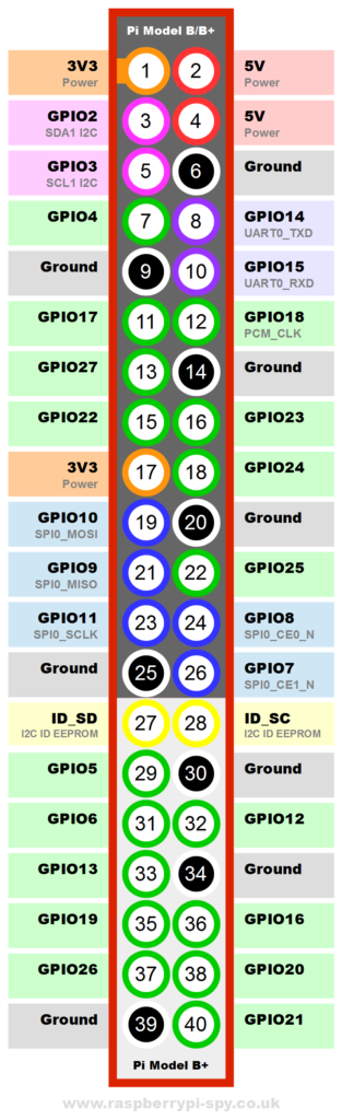
      Diagram

      Here is a diagram showing all 40-pins :

      Raspberry Pi Model B+ GPIO Header Pin-out


      Additional GPIO

      The B+ offers 9 extra GPIO pins which can be configured as inputs of outputs. This brings the total number to 26 (17+9).

      Ground Pins

      The extended header offers an additional 3 ground pins. So that’s a total of 8.

      Worksheet

      Raspberry Pi Model B+ GPIO Header Pin-outReferring to information on a webpage is great but when you are hardware interfacing it is still useful to be able to scribble on a piece of paper. I’ve created a printable Model B GPIO worksheet so that you can draw and write on the diagram as you build your projects.

      It makes it much easier to remember what wires, sensors and components you’ve got connected to each pin.


      Share. Facebook Twitter Pinterest LinkedIn Tumblr Email
      Previous ArticleIntroducing the Raspberry Pi Model B+ Single Board Computer
      Next Article Raspberry Pi Model B+ And Addon Board Compatibility

      Related Posts

      Using a Level Shifter With the Raspberry Pi GPIO

      12 inch GPIO Zero Ruler from RasPi.TV

      RasPiO GPIO Quick Reference Ruler for Raspberry Pi

      14 Comments

      1. Dominique on July 23, 2014 12:15 pm

        Can I reuse your GPIO diagramme (with source) to complete our documentation page available here?

        http://mchobby.be/wiki/index.php?title=Rasp-Hack-GPIO_Connecteur#Les_broches_27_.C3.A0_40

        Reply
        • Matt on July 23, 2014 12:33 pm

          Hello, yes that is OK!

          Reply
      2. Christian Uhl on August 28, 2014 7:54 pm

        Hello!

        Thank you very much for this good diagram.

        Perhaps you could add a hint how to find Pin1 on Model B+? It isn’t marked there like it was on the previous model, as far as I can see.

        I now located it by comparing it to the previous Model and also http://mchobby.be/wiki/index.php?title=Rasp-Hack-GPIO_Connecteur#Les_broches_27_.C3.A0_40 helped, however a simple picture or drawing would surely ease finding it.

        Thanks again.

        Christian

        Reply
        • Matt on August 29, 2014 6:47 pm

          Hi Christian, if you look on the reverse of the PCB Pin 1 has a square pad and the others have round pads.

          Reply
          • Christian on September 27, 2014 7:59 pm

            Thank you very much for that hint. (-:

            Reply
      3. GILBERTO HERNANDEZ on November 12, 2014 8:50 pm

        En el pinout de la raspbeery pi b+ (27 y 28) se puede colocar un microcontrolador para que pueda leer la eeprom sd o los puertos usb?

        Reply
      4. Erk on November 16, 2014 11:45 pm

        I’m trying to address the GPIO in board mode:

        GPIO.setmode(GPIO.BOARD)

        I can't seem to figure out how to address the ports in that mode. I've tried referring to them as they are on the diagram e.g. GPIO4 or P4 or even just "4" and I get errors every time. Any suggestions?

        Thanks!

        Reply
        • Matt on November 18, 2014 3:11 pm

          BOARD mode means you refer to pins with the pin numbers rather than references. So GPIO4 is Pin 7. In BOARD mode using 4 will be referring to pin 4 which is a 5V power pin.

          Reply
      5. Joe on April 11, 2017 11:00 am

        Could you post one for the pi zero please.

        Reply
        • Matt on April 11, 2017 5:32 pm

          The header on the Pi Zero is the same as on the A+,B+,Pi 2 and Pi 3.

          Reply
      6. Jack Homeyer on January 17, 2018 8:37 pm

        What do the colours mean? It is clear that Red is 5V, Orange is 3V3, and White is Ground. Put why are GPIO Blue, Green, Purple, and Violet

        Reply
        • Matt on January 19, 2018 1:39 pm

          The colours represent groups of pins that can perform special functions. Blue is the SPI interface, Green are general GPIO, purple is the serial interface and violet is the I2C interface.

          Reply
      7. Jeff Kissinger on March 22, 2020 8:52 pm

        This pinout doesn’t match my Raspberry Pi 3B. Below is the gpio output from my Pi. Do you know why:

        pi@remotepower:~ $ gpio readall

        [removed output]

        Reply
        • Matt on March 22, 2020 11:42 pm

          My diagram is correct. For example if we take physical pin 37 the “gpio” utility labels this as “GPIO.25” when it IS GPIO26. This is probably because of some obscure technical reason which no one cares about. Pin 37 is GPIO26. In the “gpio readall” output the “BCM” column is correct when talking about “GPIO” references. I would ignore the “GPIO.” text in the “Name” column as it won’t help at all.

          A better tool to use on the command line is the official “pinout” command. This will agree with my diagram.

          Reply

      Leave A Reply Cancel Reply

      This site uses Akismet to reduce spam. Learn how your comment data is processed.

      Recent Posts
      June 30, 2022

      Pi Pico W Launched

      May 6, 2022

      Add Kodi to RetroPie Menu

      February 26, 2022

      Disable Auto-login in Raspberry Pi OS

      February 2, 2022

      Raspberry Pi Cloud Storage with MEGA

      January 7, 2022

      RetroPie Temperature Monitor from Menu

      Categories
      • 1-wire
      • 3D Printing
      • Add-ons
      • BBC Micro:bit
      • BerryClip
      • Books
      • Camera Module
      • Cases
      • Events
      • General
      • Hardware
      • I2C
      • Infographics
      • Interfaces
      • Minecraft
      • Model A+
      • Model B+
      • News
      • Pi Models
      • Pi Pico
      • Pi Zero
      • Power
      • Programming
      • Python
      • Raspberry Pi OS
      • Raspbian
      • RetroGaming
      • Robotics
      • Sensors
      • Software
      • SPI
      • Tutorials & Help
      Tags
      3D Printing Arduino audio battery berryclip Birthday bluetooth cambridge camera CamJam DigiMakers display games GPIO I2C interface Kickstarter LCD LED Linux media Minecraft Model A Model B motionEyeOS PCB photography photos Pi-Lite portable power python Raspberry Jam Raspberry Pi Bootcamp raspbian Retrogaming retroPie screen SD card security sensor SPI temperature ultrasonic video
      Raspberry PI Related
      • Adafruit Blog
      • Average Maker
      • Official RaspBerry Pi Site
      • Raspberry Pi Pod
      • RasPi.tv
      • RaspTut
      • Stuff About Code
      Tech Resources
      • MattsBits – Pi Resources
      • Microbit Spy
      • Technology Spy
      Archives
      About

      Unofficial site devoted to the Raspberry Pi credit card sized computer offering tutorials, guides, resources,scripts and downloads. We hope to help everyone get the most out of their Pi by providing clear, simple articles on configuring, programming and operating it.

      Popular Posts
      September 19, 2014

      Top 5 Reasons The Raspberry Pi Sucks

      July 27, 2012

      16×2 LCD Module Control Using Python

      October 20, 2013

      Analogue Sensors On The Raspberry Pi Using An MCP3008

      Recent Posts
      June 30, 2022

      Pi Pico W Launched

      May 6, 2022

      Add Kodi to RetroPie Menu

      February 26, 2022

      Disable Auto-login in Raspberry Pi OS

      Facebook Twitter Instagram Pinterest YouTube RSS

      Entries RSS | Comments RSS

      This site is not associated with the official Raspberrypi.org site or the Raspberry Pi Foundation. Raspberry Pi is a trademark of the Raspberry Pi Foundation.

      Copyright © 2022 - All Rights Reserved - Matt Hawkins

      Type above and press Enter to search. Press Esc to cancel.