
The BH1750 device is a digital light sensor which uses the I2C interface. This allows it to be connected to the Raspberry Pi with only four wires.
The module allows quick and cheap ambient light level measurement and the light level can be read from it as a digital number due to the built in 16-bit analogue-to-digital converter. The device itself is commonly used in mobile phones, LCD TVs and digital cameras.
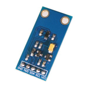
The module I’ve got measures only 32 x 16mm. I soldered a five pin header onto the PCB and this allowed me to plug it onto a piece of breadboard.
The BH1750 Ambient Light Sensor IC datasheet provides all the technical details some of which are used in my example Python script.
Configure I2C Interface
In order to use this module you must enable the I2C interface on the Raspberry Pi as it is not enabled by default. This is a fairly easy process and is described in my Enabling The I2C Interface On The Raspberry Pi tutorial.
Connecting Light Sensor Hardware to the Pi
The following table shows how I connected the module pins on the PCB to the Pi’s GPIO header (P1). Please refer to my GPIO header guide for a diagram.
| Module PCB | Desc | GPIO Header Pins |
|---|---|---|
| GND | Ground | P1-14 |
| ADD | Address select | P1-14 |
| SDA | I2C SDA | P1-03 |
| SCL | I2C SCL | P1-05 |
| VCC | 3.3V | P1-01 |
Here is a diagram of a breadboard setup. If you are connecting the module’s five pins directly to the Pi you only need five female-female wires.
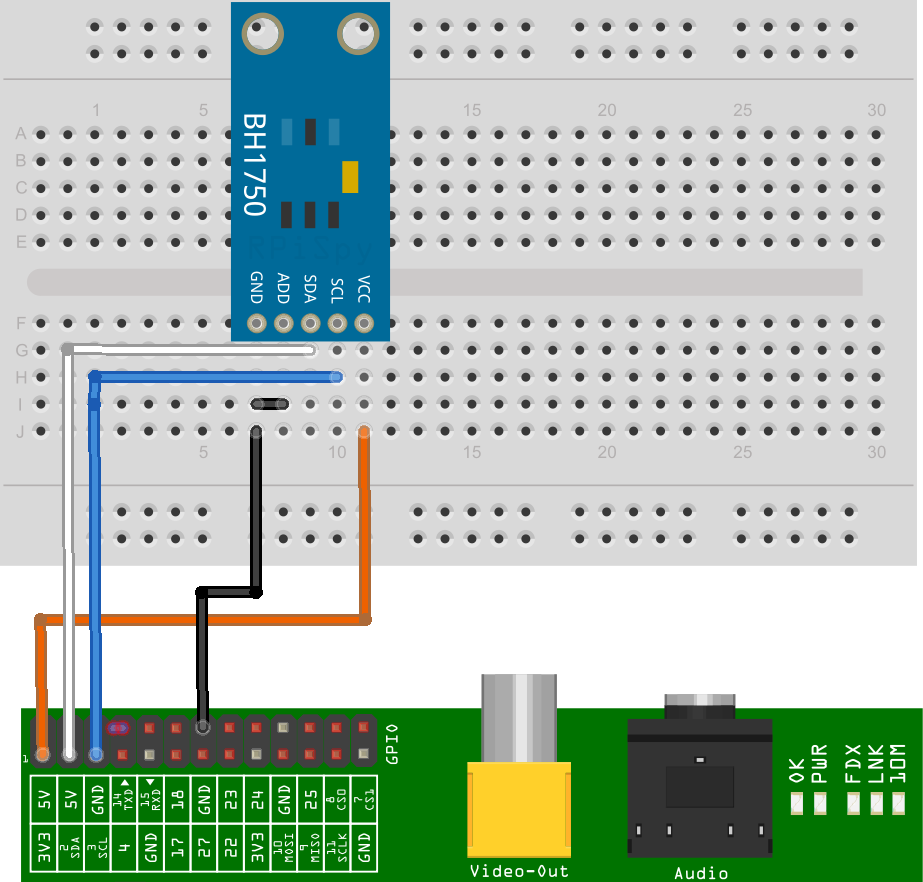
This Fritzing diagram uses a custom part I created for my module. Other modules may have a different pin arrangement so make sure you are connecting the correct pins to the Pi if yours is slightly different.
With the device connected and the Pi powered up the “i2cdetect” command should show the device with address 0x23.
Example Python Script to Show Light Level
You can download an example script to read the light level from the module and print it to the screen.
Use the following command :
wget https://bitbucket.org/MattHawkinsUK/rpispy-misc/raw/master/python/bh1750.py
or use this link in a browser.
In order to run it you can use :
python bh1750.py
or for Python 3 :
python3 bh1750.py
The output should look something like :
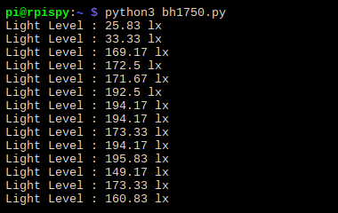
The while loop keeps taking readings every half second until you press CTRL-C.
Python Script Notes :
- The import statements import Python libraries used in the rest of the code including smbus which handles the I2C interface.
- All I2C devices must have an address. In this example I tied the ADDR pin to ground so the address used by the device is 0x23. The address becomes 0x5C if the ADDR pin is tied to 3.3V.
- The block of constants are listed in the datasheet and define the different modes the device can operate in. I define all of them but only use “ONE_TIME_HIGH_RES_MODE_1”. The other modes are only of any real interest if you need to take high speed readings.
- The “smbus.SMBus(1)” function setups the I2C interface.
- The “read_i2c_block_data” function is used to read 2 bytes of data from the device using the ONE_TIME_HIGH_RES_MODE_1.
- The convertToNumber function is then used to convert those 2 bytes of data into a number. The 1.2 value in the calculation is defined in the datasheet.
Buy a BH1750 Module
The module is available from various online sellers :
15 Comments
Great tutorial, works fine, I was wondering if you can mash this up with your BMP180 Pressure Sensor to work and log together.
Many thanks
Derek
Hello,
Im already using the GPIO ports for my touch LCD. How can i change the GPIO ports for using the sensor?
Thanks
Unfortunately you can’t change the I2C pins. But if your screen is an I2C device you can add multiple I2C devices to the same pins if they have different internal addresses.
Hi, great tutorial, thanks a lot. Works very nicely for me. I am just wondering, if anybody tried to connect more than one BH1750 to a single Raspberry. Would this be possible, e.g. using two, one with ADDR connected to GND and the for the other sensor ADDR to VCC, in order to have different addresses for the two sensors? Would it be even possible to connect more than two?
Thanks for answering my question.
If each device has a different address you will be able to use two.
Thanks for the tutorial.
Do I need to use the breadboard to connect? In this post both ADD and GND are connected to P1-06. As I am connecting the module directly to the pi I connected the ADD to P1-06 and the GND to P1-14. When I run “i2cdetect -y 1” it doesn’t show anything.
I am new to this so appreciate all your help
That should work. Both those pins are connected to ground. Double check the other connections, make sure you haven’t swapped SCL/SDA and make sure you’ve successfully completed the “Configure I2C Interface” step.
Managed to get this to work. Thank you very much for this tutorial.
I am always getting a reading of 0. Any idea why this would be the case. I can see the device connected.
when i run the file,i get the following error:-
Traceback (most recent call last):
File “bh1750.py”, line 64, in
main()
File “bh1750.py”, line 60, in main
print “Light Level : ” + str(readLight()) + ” lx”
File “bh1750.py”, line 54, in readLight
data = bus.read_i2c_block_data(addr,ONE_TIME_HIGH_RES_MODE_1)
IOError: [Errno 121] Remote I/O error
Did you follow the “Enable I2C Interface on the Raspberry Pi guide? Do you see the device address when you run the i2cdetect command? This code assumes the address of the device is 0x23. If your address is different then the reference in the code will need to be updated.
Hi,
thank you so much or this tutorial, it worked at first try! 🙂
But I was wondering: why divide by 1.2 the read value? Couldn’t find a justification on the datasheet, either…
Thank you!
The sensor has a “Measurement Accuracy” which the datasheet says varies between 0.96-1.44 but the typical value is 1.2. They expect you to update this value if you are able to calibrate the sensor. So for this example I’ve just used the typical value of 1.2 to adjust the data.
This is perfect, exactly what I was looking for, thank you. One question, though, when I leave it for a while (hours) and go back to take a reading it returns zero. if I take a subsequent reading it then returns a proper reading (now it’s something like 45236.667). I’m wondering if it’s not waking up from sleep, or something. How do I check the POWER_ON/POWER_DOWN status, then how do I tell it to do either, or RESET?
No matter which Pi use, I receive a bus = smbus(1), ‘module’ object is not callable. i2cdetect detects the sensor at 0x23 and the Pis work with other devices. Any ideas would be appreciated.
Thanks,
Bill
Have you installed python-smbus using :
sudo apt-get install python-smbus