
Following on from RobotSentry – Home Security System – Part 1 this is the second post in my security system project. With the basics of the design finished I assembled a set of components. Many of them I was able to salvage from previous projects.
Here is a list of all the items I used :
| Photo | Item | Source | Notes |
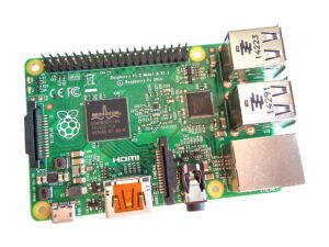 | Raspberry Pi | Farnell | Model B+ |
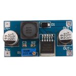 | Voltage regulator | eBay | 12V to 5V (variable) |
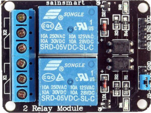 | 2 Channel Relay module | Amazon | 2-channel module |
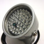 | 2 Infrared Illuminators | Amazon | 12V, 48 LED |
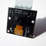 | PiNoIR Camera | CPC | Infrared Camera |
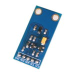 | BH1750 I2C | eBay | I2C Light sensor |
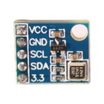 | BMP180 | eBay | I2C Temp pressure sensor |
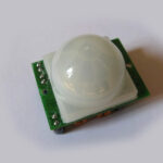 | PIR module | Amazon | |
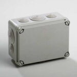 | Enclosure 175x151x95mm | CPC | Plastic IP65 |
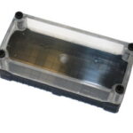 | Enclosure 80x172x53mm | CPC | Hylec, Plastic IP67 |
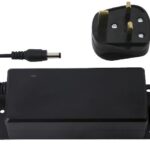 | 12V Power supply | CPC | 3.5A |
| 20m Cat5e network cable | CPC | ||
| Pi camera 50cm cable | eBay | ||
| 5mm LEDs | CPC |
To connect it together I also needed these bits :
| QTY | Item | Source | Notes |
| 2 | 330 ohm resistors | CPC | |
| 3 | 2.1mm DC barrel sockets | CPC | For illuminators |
| 2 | 2.1mm DC extension cables | CPC | For illuminators |
| 1m | 40 way ribbon cable | eBay | |
| 4 | 2×20 IDC connectors | eBay | |
| 2 | Stripboard | eBay | |
| 200 | 2.54mm male pin headers | eBay | |
| 19 | 2.54mm female pin headers | eBay | |
| 2 | 2.5mm nylon bolts | eBay | |
| 12 | 2.5 nylon round pillars | eBay | |
| 4 | 4mm nylon hex pillars | eBay |
I used a variety of suppliers but the components (or alternatives) are available from various other sellers.
Here is a photo of the external box with a ruler included for scale :
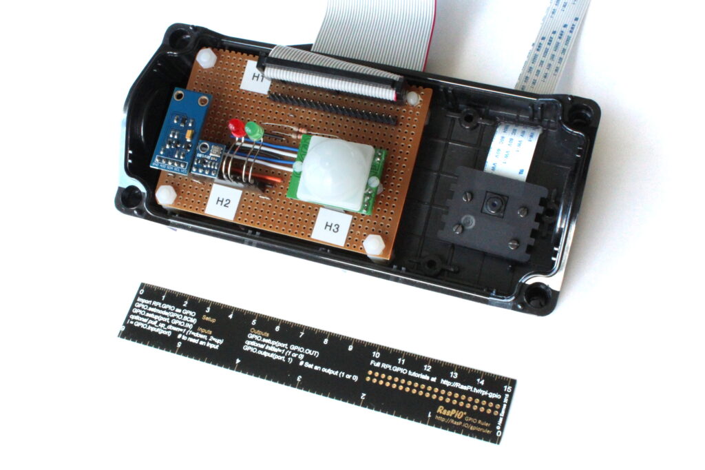
You can see (from left to right) the light sensor, pressure sensor, LEDs, PIR and camera module. This box has a clear plastic lid. This week I carried out a few tests with the PIR sensor. I had planned to mount it inside the and let it look through the transparent cover. However I found it just didn’t work behind the plastic. So this week I will cut a hole in the transparent enclosure cover and mount the sensor. The join can be sealed with silicon sealant. The camera module will be stuck to the cover and remain protected inside the box.
Here is a photo of the internal box :
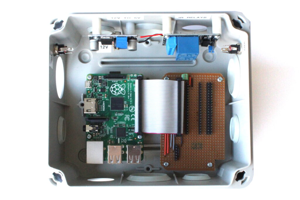
The black pin headers on the strip board are for the ribbon cable that connects to the sensor box. The barrel connectors in the top left and right will be connected to the relay module to provide power to the infra-red illuminators.
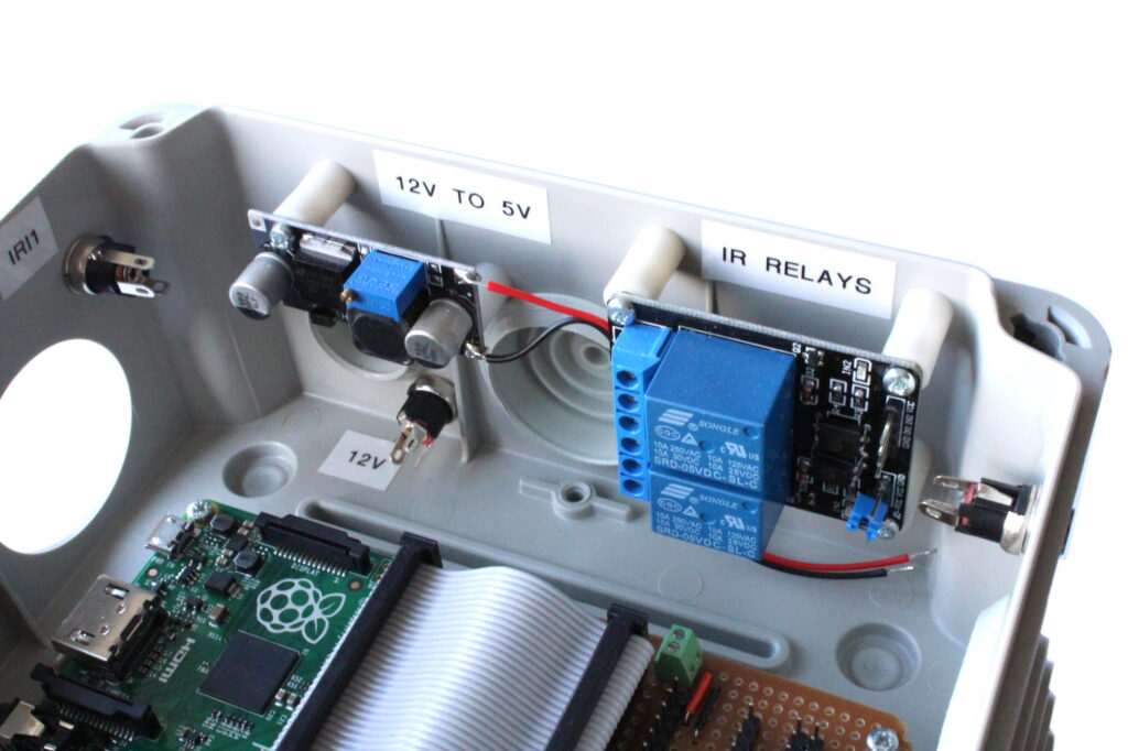
Here is a close up of the 12V to 5V regulator and 2-channel relay module which are mounted on the side :
Coming soon
The next posts in this series will be :
- RobotSentry – Home Security System – Part 3 – Hardware Testing
- RobotSentry – Home Security System – Part 4 – Installation Outside
- RobotSentry – Home Security System – Part 5 – Working System!
11 Comments
Hi Matt. Great series so far. I also coincidentally am working on a very similar system (RPI2, LED IR array, Noir Camera, PIR sensor, 2 channel relay, all powered via 12V DC to IR LEDS, and UBEC stepped down to 5V DC for the RPI). My design is intended to separate the camera, PIR sensor and IR LEDS into an outdoor (driveway) housing connected an indoor (garage) RPI control unit via a HDMI/Camera extension cable. The hardware setup for my outdoor camera housing needs some kind of adjustable mount for the camera, but I’m working on it. I’ve tested the system all wired up and it appears to work discretely. I’m now trying to work out the software design for a PIR triggered monitoring solution. Do you have any recommendations on the best approach to handling image/video capture? e.g. a single Python application which loops waiting for PIR, flipping the IR LED relay, capturing an image, repeat. Or has your previous project experience pushed you in a different direction? Thanks and I’m looking forward to your future instalments.
Just a quick follow up with my build. I found with 12V DC @ 2 Amps simply didn’t provide enough juice for just 1 of those 12 V DC IR LED arrays + the RPI. I switched to a 3 Amp power supply and its better, but not ideal. With your 3.5 Amp power supply, it would probably drive just 1 of your IR LED lights brighter than 2 units. The problem is those IR LED arrays need like 12V DC @ 2 Amps to themselves to perform reasonably unless you’re in a smallish room. With the RPI + accessories, I think you’ll find the IR lighting to be unsatisfactory.
I’m about to pull the trigger on ordering a 5 Amp power supply myself. Even if its over kill, the power supply will run cooler when everything is drawing simultaneously.
Thanks for the info. My plan was to get the system working without the IR lamps, check the relays switched ok and then introduce the lamps as required. So I might just need to keep an eye on the power consumption. I’ve got a conventional security light as well in the same area so I won’t know if I even need two IR lamps. Luckily I can always upgrade the power supply if I need to.
Hi duhmojo
Check the following 2 projects on the RPi forums – each has its benefits but I moved to Pikrellcam for stability. Both have options for triggered inputs to start recording – this could be from the PIR > GPIO running a script
RPi Cam Web Interface
https://www.raspberrypi.org/forums/viewtopic.php?f=43&t=63276
Pikrellcam
https://www.raspberrypi.org/forums/viewtopic.php?f=43&t=115583
Hi Matt,
Any progress on the next sections? 🙂
Ken
This project is almost exactly the kind of thing I’ve been looking at… any progress? 😀
It’s still on my list but I’ve got so many other things getting in the way I’m struggling to make progress with it.
This is amazing. I’m also anxious to read parts 3-5 once read. Thank you!
Looking forward to next parts as well 🙂 Thank you, btw 🙂
Still interested and I believe I’m not the only one. Have you encountered any problems or is it just the lack of a free time? Hope you’re doing well. 🙂
Another nudge to finish parts 3-5 please!