
A servo is motor that uses a set of gears to create rotary motion. Radio controlled vehicles and animation projects often use them to generate movement. They vary in size and capability but small servos are cheap and a great way to introduce movement into your Raspberry Pi projects.
This post will explain how to connect a small servo to your Pi in the easiest way possible with the minimum of hardware.
Parts
 You will need :
- A Raspberry Pi
- SD card with latest Raspbian operating system
- Small servo (TowerPro 9g or equivalent)
Servo Colour Codes
Servos generally have three wires. Two are for power and one is for the data signal. The colouring of these wires vary between manufacturers but they usually follow one of the schemes below :

Mine follow the Red/Orange/Brown scheme.
Servos and PWM
There are plenty of resources out there that explain how servos work. The important bit is that they take a PWM (Pulse Width Modulation) data signal. This is a sequence of high-low pulses where the timing between each pulse determines the rotary position.
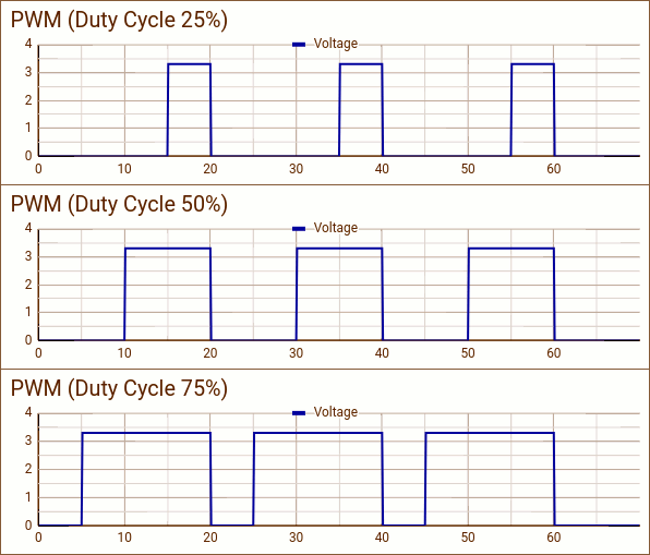
In this basic example will be using software to generate the PWM signal. This isn’t as accurate as a proper hardware generated PWM signal but good enough for the basics.
Hardware Setup
The easiest configuration is to connect the servo directly to the Pi. This is suitable for small servos that aren’t expected to perform any demanding tasks. The power will be drawn via the Pi’s 5V pin and is subject to certain limitations. If your servo draws too much current then it may affect the operation of USB devices or the Pi itself.
Any GPIO pin can be used
| Servo Wire | Colour | Raspberry Pi GPIO | Comments |
|---|---|---|---|
| Power (+) | Red | Pin 2 (5V) | |
| Signal/Data | White/Yellow/Orange/Blue | Pin 11 (GPIO17) | |
| Ground | Black/Brown | Pin 9 | Any ground pin can be used |
Any of the Pi’s ground pins can be used. Please refer to the Raspberry Pi GPIO header image to locate the additional ground pins.
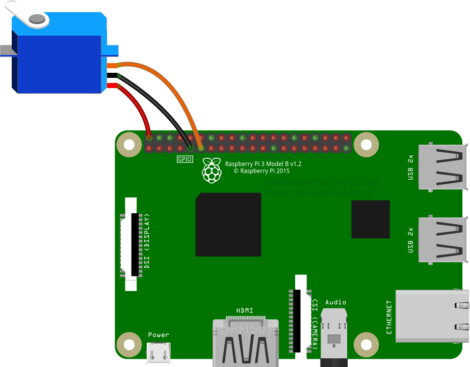
In this example I have used Pin 9 (Black) for ground. The power wire (Red) is connected to Pin 2. The signal wire (Orange) can be connected to any GPIO pin but I prefer using Pin 11 (GPIO17) because it is next to Pin 9 and it makes the wiring a bit easier. If you use a different GPIO be sure to update the example scripts with the correct number.
Example Python Servo Script #1
Once connected the easiest way to get your servo moving is to use the Gpiozero library in a Python script. It is installed by default in the latest Raspbian image.
You can use this Python script :
from gpiozero import Servo
from time import sleep

myGPIO=17

servo = Servo(myGPIO)

while True:
    servo.mid()
    print("mid")
    sleep(0.5)
    servo.min()
    print("min")
    sleep(1)
    servo.mid()
    print("mid")
    sleep(0.5)
    servo.max()
    print("max")
    sleep(1)
Copy the above code into a new text file named “servo1.py” or download directly to your Pi from my Bitbucket repository using :
wget https://bitbucket.org/MattHawkinsUK/rpispy-misc/raw/master/python/servo1.py
I recommend using wget rather than copying and pasting so you don’t lose the correct indentation.
To run the script use the following command :
python servo1.py
The servo should now move between its minimum, middle and maximum positions with a small delay in-between.
Example Python Servo Script #2 – Calibrating Range
The first script makes use of the Gpiozero defaults. It assumes the servo uses a signal frame width of 20ms. The pulse width for the minimum and maximum rotation is assumed to be 1ms and 2ms. This information should be available in the servo specification and I would avoid sellers that don’t provide this data.
I found that with the default settings my servo only moved +45/-45 degrees. I changed the pulse width parameters in order to get a full 90 degrees of rotation in either direction . The script below demonstrates this :
from gpiozero import Servo
from time import sleep

myGPIO=17

myCorrection=0.45
maxPW=(2.0+myCorrection)/1000
minPW=(1.0-myCorrection)/1000

servo = Servo(myGPIO,min_pulse_width=minPW,max_pulse_width=maxPW)

while True:
    servo.mid()
    print("mid")
    sleep(0.5)
    servo.min()
    print("min")
    sleep(1)
    servo.mid()
    print("mid")
    sleep(0.5)
    servo.max()
    print("max")
    sleep(1)
Copy the above code into a new text file named “servo2.py” or download directly to your Pi from my Bitbucket repository using :
wget https://bitbucket.org/MattHawkinsUK/rpispy-misc/raw/master/python/servo2.py
I recommend using wget rather than copying and pasting so you don’t lose the correct indentation.
To run the script use the following command :
python servo2.py
The servo should now move between its minimum, middle and maximum positions with a small delay in-between.
In this example the min pulse width is decreased from the default of 1 by a correction of 0.45 to 0.55ms. The max pulse width is increased from the default of 2 by 0.45 to 2.45ms. This gave my servo a full 90 degrees of rotation in both directions. The values “0.55” and “2.45” are divided by 1000 to convert them to milliseconds.
There is nothing magical about “0.45”. It was just the correction that worked best for my servo.
To work out these numbers I started with :
myCorrection=0
maxPW=(2.0+myCorrection)/1000
minPW=(1.0-myCorrection)/1000
and increased/decreased the correction number in increments of 0.05. This allowed me to find the biggest change I could make before the servo sounded unhappy.
“myCorrection” has to be a number between 0 and 1 but is unlikely to ever need to be 1!
Example Servo Script #3 – Precise Positioning
Once you’ve determined the min and max pulse width values you can use the “value” feature to position the servo arm anywhere between its limits.
Setting the “value” parameter to a number between -1 and +1 moves the arm between its minimum and maximum positions. Examples include :
# Minimum position
servo.value=-1

# Mid-point
servo.value=0

# Maximum position
servo.value=1

# Position between mid-point and maximum
servo.value=0.5
The script below generates a range of “value” numbers to sweep the servo between its maximum and minimum position :
from gpiozero import Servo
from time import sleep

myGPIO=17

myCorrection=0
maxPW=(2.0+myCorrection)/1000
minPW=(1.0-myCorrection)/1000

servo = Servo(myGPIO,min_pulse_width=minPW,max_pulse_width=maxPW)

while True:

  print("Set value range -1.0 to +1.0")
  for value in range(0,21):
    value2=(float(value)-10)/10
    servo.value=value2
    print(value2)
    sleep(0.5)

  print("Set value range +1.0 to -1.0")
  for value in range(20,-1,-1):
    value2=(float(value)-10)/10
    servo.value=value2
    print(value2)
    sleep(0.5)
Copy the above code into a new text file named “servo3.py” or download directly to your Pi from my Bitbucket repository using :
wget https://bitbucket.org/MattHawkinsUK/rpispy-misc/raw/master/python/servo3.py
I recommend using wget rather than copying and pasting so you don’t lose the correct indentation.
To run the script use the following command :
python servo3.py
The servo should now move between its minimum, middle and maximum positions with a small delay in-between.
The first “For” loop generates a set of integers between 0 and 20. The value has 10 subtracted from it to give a range -10 to 10. The value is then finally divided by 10 to give a range of -1 to +1. The original set of values contained 20 integers and we still have 20 steps in the sequence. To increase the number of steps to 40 you would replace 20 with 40 and subtract 20 rather than 10.
The second “For” loop does the same thing but generates a sequence from +1 back to -1.
Next Steps
Once you have these scripts working you can modify them to get the arm to move however you wish. For example you could randomly generate a number between -1 and +1 to position the arm between its maximum and minimum limits. Or perhaps move it based on input from a sensor or joystick? As long as you can convert the range of values from your sensor to a range of -1 to +1 you can indicate the result using a servo.
Take a look at the official documentation for Gpiozero for additional technical information.
Here is short video showing the servo moving using these three example scripts :
Where to Buy Small Servos
These servos are available from plenty of outlets including [Amazon] and [eBay].
You can read more about these devices on the Wikipedia page.
4 Comments
I wonder, how many servo’s could be connected this way to a single raspberry pi w, and how would one add an dedicated external power source to drive some bigger servos?
It’s hard to predict how many servos you could add as it depends on the servo and how much current it draws when it stalls. External power is fairly easy and I’m going to do another blog post covering that.
Cool, thanks a lot, this really helps me get up to speed with servos!
you can power on the servo with an external battery with + and – connected to servo on one hand
on another -and signal of servo to the pi
take care of the max voltage of the servo ( 5v for digital one )
regards