
Miniature OLED display modules are a great way to add a small screen to your Raspberry Pi projects. They are available in various sizes but common sizes include 128×32 and 128×64 pixels. The cheaper ones have single colour pixels that are either white, yellow or blue. My device has white pixels and uses an I2C interface which only requires four wires to be connected to the Pi.
In this tutorial I’ll explain how I setup my 0.96″ OLED display module using the Pi’s I2C interface. Once setup it is easy to use Python to place text, draw shapes or even display simple images and animations.
UPDATE: This article has been updated to remove references to Python 2 and switch to luma.oled library.
The OLED Module
My OLED display module is a 0.96″ I2C IIC SPI Serial 128X64 OLED LCD LED Display Module.
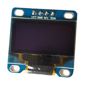
It has four pins. Two are power (Vcc and Gnd) and two are for the I2C interface (SDA and SCL). The header may need to be soldered on before you can use it.
Update Operating System
As with all my projects I started off by creating an SD card with the latest Raspbian image. Then I made sure this was up-to-date by running the following commands :
sudo apt update
sudo apt upgrade
This step may take a few minutes if there are lots of packages to update but it usually saves some frustration in the future.
Display Module Setup
My screen had four pins, two for power and two for the I2C interface.
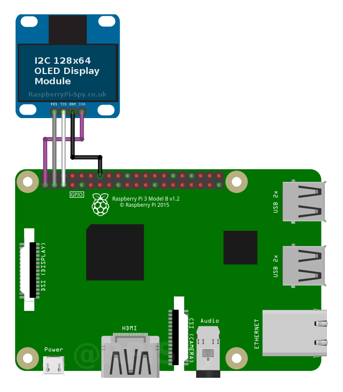
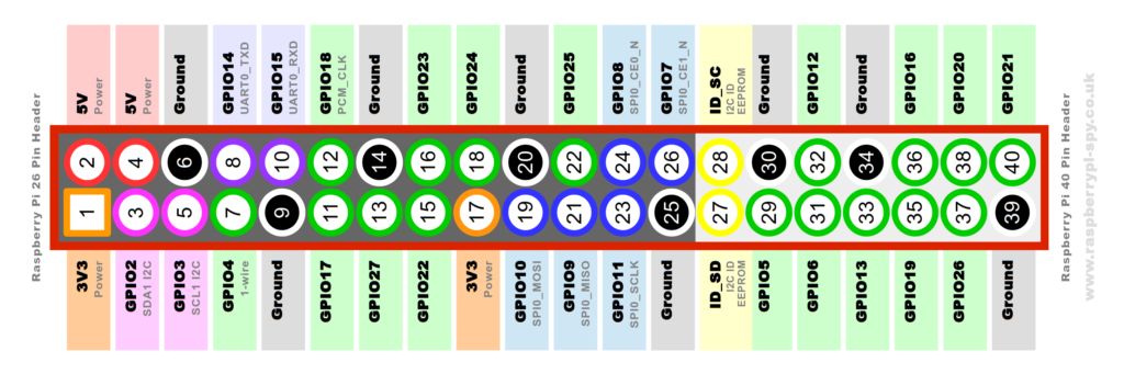
I connected them directly to the Raspberry Pi’s GPIO header using the following scheme :
| OLED Pin | Pi GPIO Pin | Notes |
|---|---|---|
| Vcc | 1 * | 3.3V |
| Gnd | 14 ** | Ground |
| SCL | 5 | I2C SCL |
| SDA | 3 | I2C SCA |
* You can connect the Vcc pin to either Pin 1 or 17 as they both provide 3.3V.
** You can connect the Gnd pin to either Pin 6, 9, 14 , 20, 25, 30, 34 or 39 as they all provide Ground.
Enable I2C Interface
The I2C interface is disabled by default so you need to enable it. You can do this within the raspi-config tool on the command line by running :
sudo raspi-config
For additional details on this step please see my how to Enable the I2C Interface on the Raspberry Pi post.
The following libraries may already be installed but run these commands anyway to make sure :
sudo apt install -y python3-dev
sudo apt install -y python3-smbus i2c-tools
sudo apt install -y python3-pil
sudo apt install -y python3-pip
sudo apt install -y python3-setuptools
sudo apt install -y python3-rpi.gpio
sudo apt install -y python3-venv
I would recommend using Python 3 unless you have a really good reason for using Python 2.
Finding the OLED Display Module’s Address
With the I2C libraries installed I used the i2cdetect command to find the module on the I2C bus.
i2cdetect -y 1
and I got the following result :
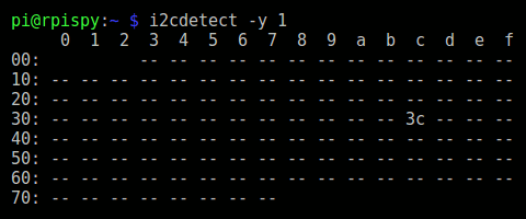
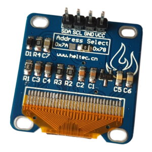
This was good news as it showed the device had been detected with an address of “0x3c”. This is the default hex address for this type of device. I’ve got no idea why the device PCB suggests the address is “0x78” when it is clearly “0x3c”.
If you’ve got an original Model B Rev 1 Pi then type the following command instead :
i2cdetect -y 0
Create Project Folder
Now the hardware is working create a folder to contain items related to the screen.
cd ~
mkdir oled-screen
cd oled-screen
Create Python Virtual Environment
In order to install the luma.oled library we will first create a Python Virtual Environment. This will allows all the libraries and dependencies to be contained in a single directory, protecting your core Python installation from conflicts. If anything goes wrong you can delete the virtual environment without needing to re-image your entire SD card.
To create a Python 3 virtual environment in a sub-folder named “venv” use:
python3 -m venv venv
This creates a self-contained Python 3 system. Activate it using:
source venv/bin/activate
You should notice the name of the virtual environment appear in front of your command prompt.
While activated any Python libraries that are installed will be installed in this virtual environment and not interfere in your default Python installation.
Note: We created a Python 3 environment so going forward any use of “Python” will automatically refer to Python 3.
Install Luma OLED Python Library
To install the library run the following command:
python -m pip install --upgrade luma.oled
Install Luma Examples
It’s worth installing the Luma examples as they will allow you to test your screen.
Check we are in the project folder:
cd ~/oled-screen
Then ensure git is installed:
sudo apt install -y git
Then clone the examples repository:
git clone https://github.com/rm-hull/luma.examples.git
The following dependencies may need to be installed for the examples to work correctly:
sudo apt install -y python3-pil libjpeg-dev zlib1g-dev python3-av
sudo apt install -y libfreetype6-dev liblcms2-dev libopenjp2-7 libtiff5 -y
Now we should be able to run some examples:
cd luma.examples
cd examples
List the examples with:
ls
Finally run an example of your choice. Good examples are:
python 3d_box.py
or
python crawl.py
By modifying these examples you can create your own scripts for your projects.
To get the “sys_info.py” example to run I needed to run:
pip install psutil
Deleting the Python Virtual Environment
The useful feature of Python Virtual Environments is that you can delete the folder and remove all the changes that were made by installing libraries using “apt” and “pip”. Earlier in this article we created the folder “luma-env” within our “oled-screen” project folder. To remove the virtual environment
rm -rf ~/oled-screen/venv
This will leave the oled-screen folder and any other files in it.
Increasing I2C Bus Speed
If you are using your OLED screen for animations or videos it is worth increasing the bus speed of the interface as it can improve performance. Please see the Change Raspberry Pi I2C Bus Speed post .
Troubleshooting
If your screen isn’t working you should start at the beginning of this tutorial and work through it. Here are some thing to consider :
- Did you enable I2C and install “python3-smbus” and “i2c-tools”?
- Are the four module connections correct? Did you get SDA and SCL mixed up?
- Did “i2cdetect -y 1” give you the address of the display on the I2C bus?
- If your screen is using an address other than 0x3c did you adjust the Python script?
Buy a Miniature OLED Screen
These screens are available from a number of retailers so take a look and pick one that is convenient for your location :
Read the descriptions carefully as some OLED display modules use the SPI interface rather than I2C. Those are fine but you’ll need to follow a different tutorial to use that style.
Some of the product links on this page are affiliate links. I receive a small commission based on purchases made via these links. The price you pay is the same.
42 Comments
Thanks Matt. This has been a really helpful tutorial. There is very little info regarding these little screens beyond setting them up. This is far and away the most concise and well explained tutorial I have read about displaying your own images.
Hello,
Thank you for the helpful tutorial.
I have a problem while installing the python library. When i execute the command
sudo python setup.py install
i get the following output:
Extracting in /tmp/tmpoaIjab
Traceback (most recent call last):
File “setup.py”, line 4, in
use_setuptools()
File “/home/pi/Adafruit_Python_SSD1306/ez_setup.py”, line 128, in use_setuptools
return _do_download(version, download_base, to_dir, download_delay)
File “/home/pi/Adafruit_Python_SSD1306/ez_setup.py”, line 108, in _do_download
_build_egg(egg, archive, to_dir)
File “/home/pi/Adafruit_Python_SSD1306/ez_setup.py”, line 57, in _build_egg
with archive_context(archive_filename):
File “/usr/lib/python2.7/contextlib.py”, line 17, in __enter__
return self.gen.next()
File “/home/pi/Adafruit_Python_SSD1306/ez_setup.py”, line 88, in archive_context
with get_zip_class()(filename) as archive:
File “/usr/lib/python2.7/zipfile.py”, line 770, in __init__
self._RealGetContents()
File “/usr/lib/python2.7/zipfile.py”, line 813, in _RealGetContents
raise BadZipfile, “File is not a zip file”
zipfile.BadZipfile: File is not a zip file
and library does not install. How can I solve this? Thank you!
There seems to be an issue with a missing file. Someone has raised this on the Adafruit github page and they have assigned the issue for someone to investigate. https://github.com/adafruit/Adafruit_Python_SSD1306/issues/22. Hopefully they will resolve it soon.
Is it possible to connect two screens?
It should be possible, but you would need a screen that allowed you to change the default I2C address. Some allow this by soldering two contacts together.
Hi Ivan, you can get an I2C multiplexer to add 8 screens. I think you can get 2 x 8 channel multiplexers to 16 screens working
Matt- The reason why the PCB said 0x78 and you’re reading 0x3C from i2c-tools is:
I2c-tools shifts the entire address to the left by 1 (adding the last bit for R/W). Shift 0x3C to left by 1 gives you 0x78 (and obviously vise versa).
All the best!
Thanks for explaining that. I’ve just Googled it and understand now. 0x3c is these 7 bits 111100 but once the R/W bit is included it becomes these 8 bits 1111000 which is 0x78.
I had to install python3-dev before the setup script ran ok. *sudo apt-get install python3-dev*
python3-dev should already be installed in the latest Raspbian image.
Not in the `-lite` image.
Also needed `setuptools`, Image/PIL/pillow (?!), and RPi.GPIO, but I couldn’t get them all installed at this time, so I gave up for now.
I’ve just used this guide on a project and have made some updates. I think you have to install more libraries if using Raspbian Lite.
Thanks for the tutorial – had my screen up and running in about 30 seconds with your excellent direction
THANK YOU SOOOO MUCH!
I tried to get it work for hours with the official tutorial of the screen, but it was far to complicated and did’nt work.
Luckily i found this Tutorial, it saved me from a lot of wasted time <3
Hello! This is really great and I got it to work perfectly. I was wondering where I would be able to change the GPIO pins as I want to set my relais there (respectively the setup forsees so).
I couldn’t find the Pins 1,3,5,14 anywhere assigned in the code.
Thanks for your help.
1 and 14 are 3.3V and Ground. You can use any of the other power pins on the header :
There is only 1 other 3.3V pin and that is pin 17. There are plenty of Ground pins.
The I2C pins are the defaults. You can configure a new software I2C interface by editing the /boot/config.txt file and adding :
dtoverlay=i2c-gpio,i2c_gpio_sda=5,i2c_gpio_scl=6This would set up a new interface at /dev/i2c-3. However I’ve never tried this myself.
To detect the device on the new interface you can use :
i2cdetect -y 3thank you MATT, I edited to config.txt and got an output from the i2cdetect -y 3 command, but the result was empty… meaning no detection.
I am assuming that with i2c_gpio_sda=5 and i2c_gpio_scl=6 pins 5 and 6 are meant, I would change these to let’s say 19 and 21?
Then again, I read something about a BUS and that I could control different interfaces with sam pins… ughhh. difficult & clueless I am
With the dtoverlay the numbers are GPIO references not physical pin numbers. So i2c_gpio_sda=5 means GPIO5, physical pin 29.
This is extremely helpful.
I have one OLED running stats.py fine, and would like to add a second OLED with another script running, like shapes.py or animate.py.
Assuming I set up the second software I2C using the steps above, how do I then ‘point’ the second script to run on the second OLED? Do the scripts default to run on y 1 / 0x3c, and it’s just a case of manually editing the script to look for the new device?
minor typo:
it should spell “sudo apt-get upgrade” and not “ugrade”
Well spotted. I have updated the text 🙂
Is the screen compatible with the Raspberry Pi Zero?
It works via I2C so should work just fine on the Pi Zero.
Hi, fantastic tutorial – very clear!
I was wondering if you would know why when using this i2c screen it seems to effect my ability to also use a DS18B20 temperature sensor? (DS18b20 connects to BCM 4 using the One-Wire (w1) protocol).
Before detecting the OLED, when I run the following in cmd:
cd /sys/bus/w1/devices
ls
It returns a serial number (28-xxxx).
After I connect the i2c screen it seems to replace the temp sensor – replaced with a set of DS18b20 unrelated serial numbers… Any thoughts on what’s going on would be greatly appreciated!
I’ve got an OLED display that displays in blue/yellow – it’s also based on the 1306. How would I make an image that makes use of both of those colours? I’m guessing use two colours in the image file, but which ones?
Silly question, but I’m new to all this!
I haven’t got one of those blue/yellow boards but I suspect the colour is fixed in particular zones of the screen. I’ve only ever seen the different colours at the top and bottom of the screens.
how do you chang the screen size as you stated from 128×32 to 128×64 i cant figure how to do it please help
Edit the example python script using a text editor and make the change as described in the “Screen Size Adjustment” section. You can edit the example scripts on the command line using :
sudo nano shapes.pyMake the change and then save/quit using CTRL-X, Y then ENTER.
Hello, Followed this and almost got it working only issue I am presented with is right at the end. See below. If anyone could help would be much appreciated.Traceback (most recent call last):
File “monitor.py”, line 26, in
from PIL import Image
ImportError: No module named PIL
Did you start with the latest version of Raspbian? I ran through this post myself when I was rebuilding my Pi-Hole system. I seem to remember making some changes to the list of package installs due to a change in the PIL package.
Regarding my last post, about a problem connecting with i2c to the display … I found that one of my breadboard wires was not conducting. It works fine. Thanks for the tutorial. Sorry if I wasted your time thinking about my post.
THank you for your tutorial . I managed to get my OLED screen to work on my Pi3 but cant get it to work on the Pi zero w.
After doing every step by step initially on the zero it wouldnt show up on the oled detect command. I then put the SD card into my Pi3 and it did detected the screen plus the examples straight away.
Is there something i missed with the set up for the zero which is stopping this?
Did you try
i2cdetect -y 0?Matt
I’ve just resolved it by running ‘pip3 install Adafruit-BBIO’ just a guess. the screen worked immediately
Thanks
is it possible to set up 2 oled display on a Pi Zero?
I2C allows multiple devices on the same bus as long as you can give each device a unique ID. If your screen allows you to change to an alternative address you should be able to run two on the same pins.
Hi Matt, I’ve got a 128×32 screen from PiHut, and I’ve been able to install and run as you suggest above. But when I run the stats.py, I get the variables preceded by a b’ and followed by \n’. I can’t see where these added characters are coming from.
i’ve the exact same problem but with an 128×64 and i can’t see the solution…
Just found the solution after commenting -.-
https://stackoverflow.com/questions/37016946/remove-b-character-do-in-front-of-a-string-literal-in-python-3
you need to decode the string you want to display as utf-8
HI THERE WELL I GOT THE OLED TO WORK. BUT MY ISSUE IS IR DOES NOT WORK WHEN I REBOOT MY PI? WHAT HAVE I DON WRONG?LOL
If you want a script to run when your Pi reboots you need to launch the script autonatically.
You can do this using cron:
crontab -eand adding the following line to the end :
@reboot python3 /home/pi/stats.py &You cron file will look like this :
# For more information see the manual pages of crontab(5) and cron(8)#
# m h dom mon dow command
@reboot python3 /home/pi/stats.py &
Save and exit using CTRL-X, Y then ENTER.
Obviously replace “stats.py” with the name of the script you want to run.
Working perfectly in 2025. Perfect instruction. Many thanks.