
In previous posts I’ve covered using HD44780 16×2 and 20×4 LCD screens with the Raspberry Pi using Python. These are relatively easy to use but require a number of connections to be made to the Pi’s GPIO header. This setup can be simplified with the use of an I2C enabled LCD screen.
These can either be purchased as a complete unit or you can attach an I2C backpack to a standard screen.
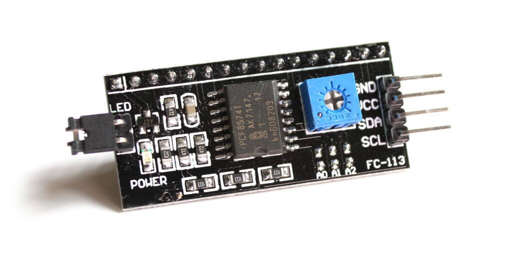
Here is an I2C backpack :
and here is a backpack soldered to the back of a standard 16×2 LCD screen :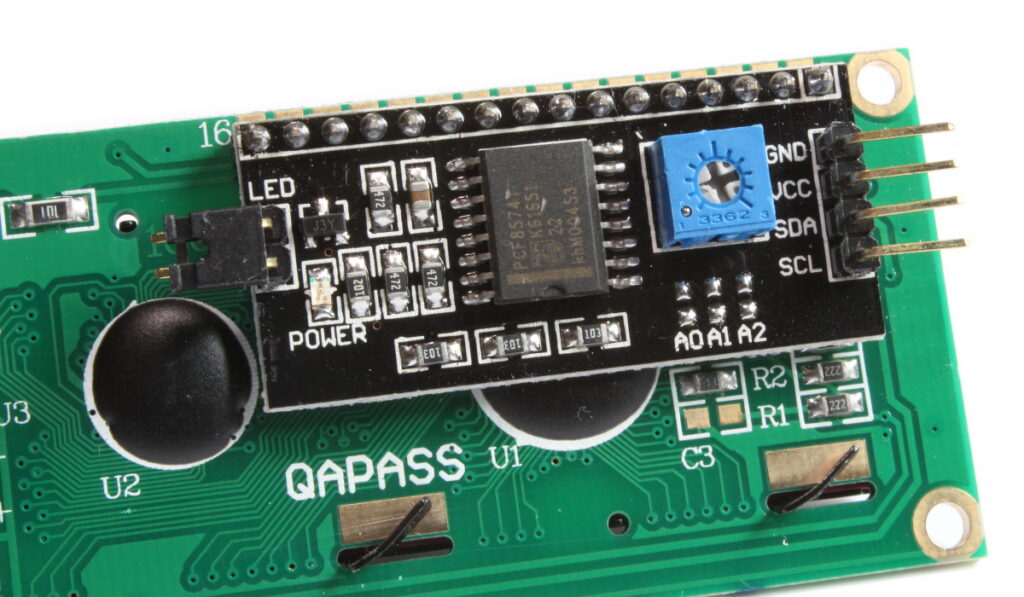
It requires 16 solder points but once done the screen can be attached to the Pi with only four wires!
Step 1 – Connect LCD Screen to the Pi
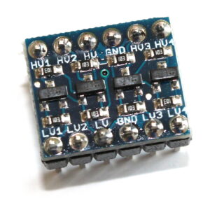 The I2c module can be powered with either 5V or 3.3V but the screen works best if it provided with 5V. However the Pi’s GPIO pins aren’t 5V tolerant so the I2C signals need to be level shifted. To do this I used an I2C level shifter.
This requires a high level voltage (5V) and a low level voltage (3.3V) which the device uses as a reference. The HV pins can be connected to the screen and two of the LV pins to the Pi’s I2C interface.
| Level Shifter | Pi | I2C Backpack |
|---|---|---|
| LV | 3.3V (pin 1) | – |
| LV1 | SDA (pin 3) | – |
| LV2 | SCL (pin 5) | – |
| GND | GND (pin 6) | GND |
| HV | 5V (pin 2) | VCC |
| HV1 | SDA | |
| HV2 | SCL |
While experimenting I found that it worked fine without the level shifting but I couldn’t be certain this wasn’t going to damage the Pi at some point. So it’s probably best to play it safe!
Step 2 – Download the Example Python Script
The example script will allow you to send text to the screen via I2C. It is very similar to my scripts for the normal 16×2 screen. To download the script directly to your Pi you can use :
wget https://bitbucket.org/MattHawkinsUK/rpispy-misc/raw/master/python/lcd_i2c.py
Step 3 – Enable the I2C Interface
In order to use I2C devices you must enable the interface on your Raspberry Pi. This can be done by following my “Enabling The I2C Interface On The Raspberry Pi” tutorial. By default the I2C backpack will show up on address 0x27.
Step 4 – Run LCD Script
The script can be run using the following command :
sudo python lcd_i2c.py
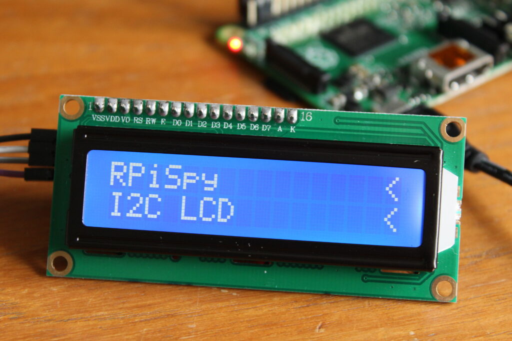
Finally you should see something like this :
Troubleshooting
If you are having problems then :
- Double check your wiring
- Start from a fresh Raspbian image
- Make sure you set up I2C as mentioned in “Enabling The I2C Interface On The Raspberry Pi” tutorial
- Follow the “Testing hardware” section in the above I2C tutorial and check the screen is detected
- Ensure SDA and SCL are correctly wired to Pins 3 and 5 on the Pi
- Adjust the contrast ratio using the trimmer on the i2c backpack
27 Comments
On the backpack shown (and on the one I use) there is an NPN transistor connected to pin 16, which controls the backlight – as you’ve implemented in your previous posts. The backlight can be turned off by setting LCD_BACKLIGHT = 0 in your script.
Also, some backpacks use i2c address 0x3f, not 0x27.
Most backpacks use the PCF8547 or 8547A chip; typically a pack using 8547 will default to 0x27, using the 8547A to 0x3F. On my backpacks (cheapo Chinese things) there are three pairs of pads marked A0, A1, A2 which can be used to change the address. Linking the two pads for each sets the relevant bit to zero, so you can set the backpack in the range 0x20 – 0x27 (8547) or 0x38 – 0x3F (8547A) . As you might expect, A0 is LSB, A2 is MSB – on my packs, anyway!
Thanks MIKE. if not for you, i couldn’t have realized my i2c pack address is 0x3f.
Hi,
Your lcd_i2c.py contains somes typos on lines 42-43 (#comments): they say the opposite as lines 74-75.
Thanks a lot, I’m using it right now.
Thanks I’ve corrected the typos now.
Thank for script! It really helps to start fast with 1602 lcd connected to rpi using i2c bus.
Personally, I’m planning to utilise it in my network audio player project (build with rpi 2, volumio and hifiberry dac).
However, I’ve noticed that sometimes, when script starts, display shows corrupted random characters instead of normal strings.
For example this may fail, may not:
lcd_string(strftime(“%H:%M:%S”, gmtime()), LCD_LINE_2)
Also more detailed comments in script would be very helpful!
Isn’t the level shifter a bit unnecessary? The SDA and SCL pins are outputs from the Pi, so they are sending out 3.3v logic levels, not receiving them? As long as the backpack can cope with 3.3v logic, and +5 to the PCF8574 + LCD you should be fine. The code works fine so thanks!
Great, the first “proper” demo that I managed to get to work first time! Thanks a lot!
Thanks Matt!
This seems to be the only script that worked for me so far.
I still have a “challenge” and hope you can help here.
The root cause is that I’m a total noob in terms of Python.
I need your script to read the content of the text file (I did it already and it’s ok) when launched and pass the selected content as a static text (in this case artist and song title) to the screen and that’s it. The script will be automatically launched by the player (MoOde audio) when something changes (it’s covered by the player itself, where I can define the script I want to launch). Once this is working – I’m happy and can start thinking about more advanced level, where this text will be scrolled when can’t fit the screen.
Thanks in advance!
Great work, you saved me precious time!
I modified your lcd_string function to make it easier to use as a library, now it can accept the line number from 0 to 3:
def lcd_string(message,line): # Send string to display if line==0: line=LCD_LINE_1 if line==1: line=LCD_LINE_2 if line==2: line=LCD_LINE_3 if line==3: line=LCD_LINE_4 message = message.ljust(LCD_WIDTH," ") lcd_byte(line, LCD_CMD) for i in range(LCD_WIDTH): lcd_byte(ord(message[i]),LCD_CHR)Great Demo however I`m get the error below and was wondering if anyone could shed some light on . It`s on an up to date pi3
Traceback (most recent call last):
File “lcd_i2c.py”, line 135, in
lcd_byte(0x01, LCD_CMD)
File “lcd_i2c.py”, line 83, in lcd_byte
bus.write_byte(I2C_ADDR, bits_high)
IOError: [Errno 5] Input/output error
You get that error when i2c isn’t enabled or the device hasn’t been found on the i2c bus. Does it show up when you run the i2cdetect test?
Im stuck on reading the table in the “Connect Screen to the Pi”, how would I connect the Raspberry pi direct to the I2C Backpack without the Level Shifter? I have a Level Shifter coming, but its in the post from china and could take weeks, I would like to get started having a play around without it for now. I have a pi 1.
Thank you.
Just connect SDA (pin 3) and SCL (pin 5) to the appropriate pins on the backpack.
Hello
I can use this code on a lcd 20×4 ?
It should work although to use all 4 lines with 20 chars the script would need to be modified. The “width” will need to be changed from 16 to 20 and the line RAM addresses will need to be modified. Take a look at this post : 20×4 Module Control using Python
Do you still need to use a I2C level shifter?
Most, if all of the LCD’s claim to be able to work on 5v
Are they just hoping it will work?
Is it still best to fit a I2C level shifter between pi and the LCD?
The screens will work with 5V. It’s just the device will probably be using 5V on the logic pins as well. The Raspberry Pi is not tolerant to 5V on its inputs so the level shifter just guarantees the Pi never sees 5V from the screen. However, it will probably work fine without. The only way to be truly sure is to be able to measure the amplitude of the screen’s I2C signals. But without some sort of signal analyser this is difficult to do. I’ve used screens without the level shifter but I didn’t want to recommend that in case someone followed my tutorial and damaged their Pi.
Thank you for this. Worked beautifully interfacing a C.H.I.P. Pro to a 20×4 display via I2C adapter and likely saved me A LOT of time. Cheers
God bless you! You are the only person who mentioned adjusting the contrast. All the other bloggers left me for dead :o)
Thank heavens for people like you!
Thanks for a post like this, it’s really useful!
I’ve been following all the steps (with the exception of using the 5.5v port, I don’t have a shifter, so I connect the I2C LCD directly to the 3V port). It turns on and the code doesn’t break, I’m even able to use the python code to switch on and off the background light with it, but, and here is the question, I’m not able to make appear any letter on it!! :s
I tried with this code, and a different one, but same conclusion. I don’t know, maybe there’s a common mistake when using this LCD that I don’t know. Did it happen to anyone else like me, that seems to work but at the end not?
Any idea?
I’m using a Raspberry Pi 3 Model B+ with Raspbian, I have also a RFID lector connected and working to it, maybe any incompatibility?
I don’t get any error message..
Thanks!
Did you try adjusting the contrast with a screwdriver on the backpack?
Very useful trouble shooter
I just had to adjust the contrast!
Thank you ver much.
Hello, thanks for you script.
I followed your instruction but on my screen i see only squares.
I tried to switch off the backlight by editing your script and it works.
Do you know what could be the problem?
Thanks
It sounds like the contrast needs adjusting. This is usually the reason people see a square rather than the character.
The best script I have found to get the 20×4 display working and I tried lots without success. I would like some guidance on how I can display data from a csv file instead of the words. I have managed to extract the data and can print to the computer screen but can’t figure out how to output to the display. Some pointers would be great.
The SDA pin is bidirectional. With a 5V Vdd on the PCF8547 its minimum high input voltage is spec’ed at 0.7Vdd or 3.5V. The Pi has 1.8k resistors pulling up SDA and SCL to 3.3V. From what I can tell (looking at pictures, I have some on order) the backpack uses 10k pullups to Vdd. When Vdd is 5V this in combination with the 1.8k pull ups to 3.3V on the Pi will set the high voltage to about 3.6V. This is only 0.3V over the 3.3V supply and with a thevinin source resistance of 1.525k. If there is a protection diode on the output pin to 3.3V, then that diode would just barely turn on and the amount of current would be too small to do any damage…or so it would seem. I just thought I would add a little information here, no guarantees of course.