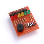
 The BerryClip+ is an enhanced version of the popular BerryClip add-on board. It is a simple, cheap and easy to use addition to the Raspberry Pi. It plugs directly onto the Pi’s GPIO header and provides 6 coloured LEDs, 1 Buzzer, 2 Switches and a 13 pin header. It can be controlled using any programming language
that can manipulate the GPIO pins and this includes Python and C.
The 13 pin header allows additional components and sensors to be added.
The kit includes the following parts :
– 1 PCB
– 1 26-way header
– 1 13-way header
– 2 Red LEDs
– 2 Yellow LEDs
– 2 Green LEDs
– 1 Buzzer
– 2 Switches
– 6 330 ohm resistors
– 2 1K ohm resistors
– 2 10K ohm resistors
– 1 Rubber bumper
Resistor Colour Codes :
330 ohm - Orange-Orange-Brown
 1K ohm - Brown-Black-Red
10K ohm - Brown-Black-Orange
 User Guide
We also have a user guide in PDF format which contains the same material as this page but may be easier for you to download and print or read on tablets and eBook readers.
Assembly Instructions
The PCB is labelled to identify where each component should be placed.
P1     : 26-way header
P2     : 13-way header
BUZZ1  : 5v buzzer
S1     : Switch (Black)
S2     : Switch (Red)
R1-R6  : 330 ohm (Orange-Orange-Brown)
R7,R9  : 1K ohm (Brown-Black-Red)
R8,R10 : 10K ohm (Brown-Black-Orange)
LED1,2 : Red LEDs
LED3,4 : Yellow LEDs
LED5,6 : Green LEDs
Bumper : Rubber bumper
Note 1: Take care to ensure the 1K and 10K resistors are placed in the correct positions.
Note 2: Take a look at the photos to ensure you solder the 26 way header onto the correct side of the board.
Note 3: The LEDs have a short leg (Cathode) and long leg (anode). Make sure the long leg is inserted into the hole nearest the P1 Header. The short leg should be inserted into the hole nearest the resistor.
Soldering
If you have never soldered before or you need a quick refresher then I can recommend the “Soldering Is Easy” comic :
http://mightyohm.com/files/soldercomic/FullSolderComic_EN.pdf
or this SparkFun page :
http://www.sparkfun.com/tutorials/106
Recommended Soldering Sequence :
- Solder 1 26-way header
- Solder 8 resistors
- Solder 6 LEDs
- Solder 2 switches
- Solder 1 buzzer
- Solder 13-way pin header
Note 4: When soldering the headers make sure you don’t use too much solder or you may short-circuit the pins underneath the PCB.
Note 5: Due to the plastic moulding the Buzzer may not lie flat against the PCB. This is normal. Don’t apply excessive force trying to push it against the board.
Once the components are soldered :
- Visually check your solder joints and ensure there are no stray blobs or splashes of solder that might short-circuit any pins.
- Remove the label on the buzzer.
- Stick rubber bumper to underside of board so it will rest on large silver capacitor (C6) on the Raspberry Pi.
- If possible use a multimeter to check there are no short-circuits between adjacent header pins.
Plug the board onto your Raspberry Pi. Stand back and admire your work.
Here is a video showing the soldering of the standard BerryClip which is very similar :
Raspberry Pi Setup
Prepare Raspbian image using official download from raspberrypi.org
Boot Pi and login with default username and password (‘pi’ and ‘raspberry’)
You will now be located in the ‘pi’ user home directory (‘/home/pi/’).
Type the following commands pressing the Enter key at the end of each line :
mkdir berryclip_plus
cd berryclip_plus
wget https://bitbucket.org/MattHawkinsUK/rpispy-berryclip-plus/get/master.tar.gz
tar -xvf master.tar.gz --strip 1
The above lines perform the following functions :
– Makes a new directory called ‘berryclip’
– Navigates into that directory
– Grabs an archive of all the files from the BitBucket.prg website
– Extracts the files to your Pi
To list the downloaded files type :
ls -l
You can use the following command to remove the gz archive as we don’t need that now we have extracted the files :
rm master.tar.gz
Run Some Example Python Scripts
The following example Python scripts are available :
- berryclip_01.py – Test LEDs only
- berryclip_02.py – Test Buzzer only
- berryclip_03.py – Test Switches only
- berryclip_04.py – Test LEDs and Switches
- berryclip_05.py – Test LEDs, Buzzer and Switches
- berryclip_06.py – LED sequence
- berryclip_07.py – Dice Simulator
- berryclip_08.py – Reaction time game
- berryclip_09.py – Random LEDs
- berryclip_10.py – Multiple LED sequences in a loop
- berryclip_11.py – Traffic light simulator
- berryclip_12.py – Morse code generator
To run a script you can use the following command :
sudo python berryclip_01.py
To quit a running Python script use [CTRL-C].
To view a text file or Python script you can use the command :
cat berryclip_01.py
Other Useful Linux Commands
To list the files in the current directory in columns use :
ls -l
To edit a script use :
nano berryclip_01.py
to save changes and quit use [CTRL-X], then [Y] then [ENTER]
To copy a script to a new filename use :
cp berryclip_01.py my_first_script.py
To reboot the Pi :
sudo reboot
To shutdown the Pi :
sudo halt
and wait for the lights on the Pi to stop changing (usually about 20 seconds) before removing the power cable.
If you are using Putty on another computer to access your Pi over a network without a monitor attached you can cut-n-paste these commands. Select the command, copy and use a right-mouse click in Putty to insert the command onto the command line.
Hardware Reference
The following list shows the mapping between the components, the header pins and the GPIO references :
LED 1    - P1-07 - GPIO4
LED 2    - P1-11 - GPIO17
LED 3    - P1-15 - GPIO22
LED 4    - P1-19 - GPIO10
LED 5    - P1-21 - GPIO9
LED 6    - P1-23 - GPIO11
Buzzer   - P1-24 - GPIO8
Switch 1 - P1-26 - GPIO7
Swtich 2 - P1-22 - GPIO25
The 13 pin header (P2) provides :
P2-01   3.3V    P1-01  3.3V
P2-02   5V      P1-02  5V
P2-03   Ground  P1-06  Ground
P2-04   GPIO2   P1-03  GPIO2   I2C0_SDA
P2-05   GPIO3   P1-05  GPIO3   I2C0_SDA
P2-06   GPIO14  P1-08  GPIO14  Serial TX
P2-07   GPIO15  P1-10  GPIO15  Serial RX
P2-08   GPIO18  P1-12  GPIO18
P2-09   GPIO27  P1-13  GPIO27
P2-10   GPIO23  P1-16  GPIO23
P2-11   GPIO24  P1-18  GPIO24
P2-12   3.3V    P1-17  3.3V
P2-13   Ground  P1-25  Ground
Be aware that some of the GPIO assignments are different on Raspberry Pi Rev 1 and Rev 2 boards. Rev 1 boards do not have the two large mounting holes in the PCB.
Rev 1 GPIO0 = Rev 2 GPIO2
Rev 1 GPIO1 = Rev 2 GPIO3
Rev 1 GPIO21 = Rev 2 GPIO27